

-
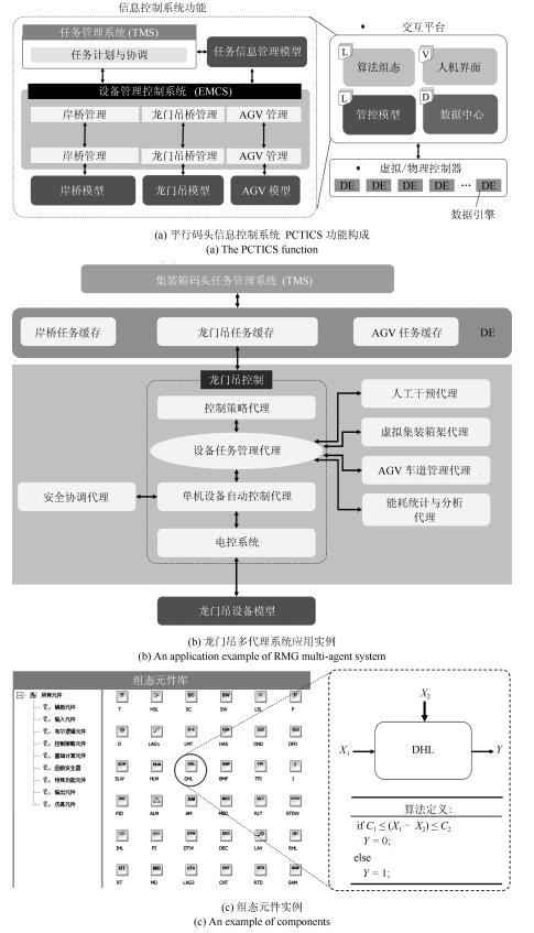
摘要: 平行系统是一种建立在人工社会和计算实验基础上的科学研究方法,它的特点是既能真实反映现实系统的动态过程,又能实时优化现实系统的控制过程.自动化集装箱码头是一类典型的复杂系统,既存在不计其数的作业方案,同时也有大量的约束条件.如何在最短时间和最低能源消耗的前提下,完成具有间歇和批次特征的集装箱转运任务,是涉及到数学、控制、管理和计算机等多个学科的重大课题.本文采用数据引擎作为人工社会中的基本计算单元,构成一个复杂的平行系统,用于自动化集装箱码头信息控制系统的研究.数据引擎作为一种面向图形化元件组态的计算环境,非常适用于复杂系统的建模与计算.在可视化和动态重构技术的支持下,利用380个数据引擎对一个具有8台岸桥、25辆AGV和16台龙门吊组成的港机系统进行了自动化作业过程的计算实验.研究结果表明,数据引擎技术是实现平行系统的有效方法,由多数据引擎组成的计算环境,能够大幅度降低自动化集装箱码头信息控制系统建模的复杂程度,能够将码头系统的管理和控制过程无缝地融合在一起.该平行系统可直接与港机设备对接,建立“人工码头”和“物理码头”之间的平行关系,从而实现对港机设备的最优控制.Abstract: Parallel systems are a kind of scientific research method based on artificial society and computational experiments, which can not only reflect the dynamic process of real system but also optimize the control process of the real system in real time. The automatic container terminal is a typical complex system having numerous operating schemes and a large number of constraints. How to accomplish the container transport task with intermittent and batch features while using minimum time and energy consumption is a major issue, which involves many disciplines such as mathematics, control, management and computer. In this paper, the data engine is used as the basic computing unit of the artificial society of parallel systems, to study the information control system of the container terminal. As a computing environment for graphical configuration, the data engine is ideal for modeling and computation of complex systems. With the support of the visualization and dynamic reconfiguration technologies, 380 data engines are used to perform computational experiments on the automation process of a port system, which consists of 8 bridge cranes, 25 AGVs and 16 gantry cranes. The results indicate the effectiveness of the data engine technology for parallel systems, and the computing environment composed of multiple data engines can greatly reduce the modeling complexity of the port information control system as well as make the information management work with the control process cooperatively. The proposed parallel systems can connect to port devices directly to establish a parallel relationship between "artificial container terminal" and "physical container terminal" so as to achieve the optimal control of the port devices.
-
Key words:
- Parallel system /
- automatic container terminal /
- data engine /
- complex system /
- multi-agents
-
旋转起重机作为常见的起重机械, 由于其结构简单、占用空间小、无需大型行走设备等优点, 因此被广泛地应用于建筑工地、矿山、港口等场合.然而, 旋臂的加减速会使负载产生摆动, 不仅降低了生产效率, 而且会损坏货物, 造成人员伤亡等.针对该问题, 已经有学者作了大量的研究, 并且提出了许多有效的方法[1-19].但是, 当负载形状不规则或者吊钩的质量不能忽视时, 该摆动会呈现出更加复杂的两级摆动现象.该现象极大地增加了系统特性分析和控制器设计的难度, 因此如何设计出可以有效抑制两级摆动的控制算法问题已经成为学术界和产业界研究的难点和热点.
近年来, 已经有学者针对起重机系统双摆抑制问题展开了一些研究[20-35]. Tang等针对2-D双摆桥式起重机系统中由于台车运动和外部风干扰而引起的荷载摆动, 提出了结合两种运动轨迹的方法, 即其中一个轨迹用来抑制台车运动引起的摆动, 另一个轨迹用来抑制风干扰引起的摆动, 仿真与实验验证了该方法的有效性[20].陈鹤等针对双摆桥式吊车系统提出了一种时间最优轨迹规划方法, 该方法在构造以时间为代价函数的基础上, 将优化问题转化成非线性规划问题, 通过仿真与实验验证了该方法的有效性[21]. Zhang等针对双摆桥式起重机在线规划了一条台车轨道, 该轨道由两部分组成分别实现双摆抑制和台车定位, 仿真验证了该轨道对于参数变化和外部干扰具有鲁棒性[22]. Huang等针对2-D双摆桥式起重机系统提出了一种新型指令整形方法, 仿真与实验验证了该方法的有效性[23].孙宁等针对双摆桥式吊车系统提出了一种基于轨迹规划的消摆定位控制方法, 该方法在充分考虑系统安全性(摆动幅值)等物理约束基础上, 通过构造新颖的平坦输出信号, 将施加在台车运动和两级摆动上的约束/指标转化为对平坦输出的约束, 从而将轨迹规划转化为凸优化问题, 通过数值仿真验证了该方法的有效性[24]. Masoud等针对双摆桥式起重机系统提出了一种频率调制输入整形方法, 该方法是由一个基于闭环系统的第一阶摆动频率的输入整形器和一个虚拟反馈控制环节构成, 仿真与实验验证了该方法的有效性[25]. Maleki等针对双摆旋转起重机系统中存在两级摆动模态的问题, 提出了一种两级模态特定不敏感输入整形器, 通过与两级模态零摆动输入整形器的比较验证了该方法的有效性, 同时也证明了其对旋臂旋转角速度与角加速度变化具有鲁棒性[26]. Masoud等针对双摆桥式起重机系统将输入整形法和闭环控制法相结合, 具体而言, 首先基于假设的双摆系统第一阶模态设计基础整形器, 再设计一个虚拟的带有积分器反馈控制器消除由第一阶模态引起的残留摆动, 通过仿真与实验验证了该方法的有效性[27]. Manning等针对2-D双摆桥式起重机系统设计了一个SI2M (Two-mode specified-insensitivity)输入整形器, 并通过与ZV2M (Two-mode zero vibration)输入整形器比较验证了所提方法对于绳长变化更具有鲁棒性[28]. Sung等针对2-D双摆桥式起重机系统中应用输入整形技术进行消摆控制时关于参数变化的鲁棒性问题, 通过比较仿真和实验指出SI2M整形器性能最好[29]. Qian等针对双摆桥式起重机消摆控制问题, 提出了一种基于SIRMs (Single-input-rule modules)的模糊控制器, 比较仿真验证了该方法的有效性[30]. Ouyang等提出了一种基于LMI (Linear matrix inequality)的简易鲁棒控制器解决双摆桥式起重机消摆控制问题[31]. Zhang等考虑了起重机系统中参数不确定性等对控制性能的影响, 提出了一个自适应控制器, 系统稳定性通过李雅普诺夫定理和芭芭拉特引理进行分析, 仿真结果验证了其有效性[32]. Tuan等针对双摆桥式起重机消摆控制问题, 提出了一个传统滑模控制器和一个多层滑模控制器, 仿真结果验证了其有效性[33]. Sun等针对双摆桥式起重机消摆控制问题, 提出了一种饱和非线性输出反馈控制器和一种非线性准PID控制, 实验结果验证了其有效性[34-35].开环控制方式[20-29], 即在设计控制器时不反馈摆角信息, 如轨迹规划法和基于输入整形技术已经应用于双摆桥式起重机系统.这些方法虽然具有控制器结构简单, 易于实现等优点, 但是它们过于依赖系统精确模型, 当系统受到外部干扰后控制性能会降低.另一方面, 虽然如文献[30-35]所提出的闭环控制方式可以为起重机系统提供鲁棒或自适应控制算法, 但是由于它们的系统阻尼比大都设定为常数.因此很难同时实现旋臂的高精度定位和两级摆角的抑制.为此, 本文将提出一种变阻尼的算法从而实现前述问题.进一步而言, 不同于2-D桥式起重机的平面摆动, 旋转起重机系统中的双摆均为圆锥摆, 系统特性更加复杂.据笔者所知, 到目前为止, 尚无针对双摆旋转起重机摆角抑制的相关报道.
本文在建立双摆旋转起重机动力学模型的基础上, 采用干扰观测器将其解耦成两个独立的线性系统, 即起伏子系统和旋转子系统.其次, 基于此线性模型分别为其设计含有非线性滑模面的滑模控制器, 并通过李雅普诺夫定理分析其稳定性.最后比较仿真和定量分析验证本文所提方法的有效性.
综上, 本文的主要创新之处可总结为如下几点:
1) 据笔者所知, 首次将具有非线性滑模面的滑模控制器应用于双摆旋转起重机系统.
2) 不同于传统的线性滑模面, 本文所提出的非线性滑模面可以为闭环系统提供一个可变的阻尼比, 从而在提高旋臂定位精度的同时实现对两级摆角的抑制.
1. 双摆旋转起重机模型
在图 1所示旋转起重机模型中$M_{0}$, $m_{1}$和$m_{2}$分别表示旋臂质量、吊钩质量和负载质量; $L$, $l_{1}$和$l_{2}$分别表示旋臂长度、悬绳长度和吊绳长度; $\theta_{1}$和$\theta_{3}$分别表示吊钩摆角和负载摆角在旋臂起伏方向上的分量; $\theta_{2}$和$\theta_{4}$分别表示吊钩摆角和负载摆角在旋臂起伏方向上的分量; $\theta_{5}$和$\theta_{6}$则表示旋臂起伏角和旋转角.
为了进一步分析和设计控制系统, 对旋转起重机做如下几点合理假设[1-3, 6-8, 28-31]:
1) 吊钩和负载均看作质点, 悬绳和吊绳的拉力和质量忽略不计.
2) 由于摆角$\theta_{i}~(i=1, 2, 3, 4)$在旋臂到达目标位置时较小, 因此$\cos\theta_{i}=1$, $\sin\theta_{i}=\theta_{i}$, $\dot\theta_{i}=0$, $\dot\theta_{i}^2=0$以及$\ddot\theta_{i}=0$等均成立.
根据拉格朗日运动方程, 双摆旋转起重机系统动力学模型如下所示:
$ \begin{align} (m_{1}+&m_{2})l_{1}^{2}(1+\theta_{1}^{2})\ddot\theta_{1}+(m_{1} +m_{2})l_{1}^{2}\theta_{1}\theta_{2}\ddot{\theta}_{2}+ \nonumber\\ &m_{2}l_{1}l_{2}(1+\theta_{1}\theta_{3})\ddot{\theta}_{3}+ m_{2}l_{1}l_{2}\theta_{1}\theta_{4}\ddot{\theta}_{4} + \nonumber\\ &(m_{1}+m_{2})l_{1}L(\cos\theta_{5}-\theta_{1}\sin\theta_{5})\ddot\theta_{5} -\nonumber\\ &\Big((m_{1}+m_{2})l_{1}^{2}\theta_{2}+m_{2}l_{1}l_{2}\theta_{4}\Big) \ddot\theta_{6}+\nonumber\\ &(m_{1}+m_{2})l_{1}^2\theta_{1}\dot\theta_{1}^2+m_{2}l_1l_2\theta_{1} \dot\theta_{3}^2+ \nonumber\\ &\Big((m_{1}+m_{2})l_{1}^2\theta_{1}\dot\theta_{2}-2(m_{1}+ m_{2})l_{1}^{2}\dot\theta_{6}\Big)\dot\theta_{2} +\nonumber\\ &(m_{2}l_{1}l_{2}\theta_{1}\dot\theta_{4}-2m_{2}l_1l_2\dot\theta_{6}) \dot\theta_{4}- \nonumber\\ &(m_1+m_2)l_1L(\sin\theta_{5}+\theta_1\cos\theta_{5})\dot\theta_{5}^2 -\nonumber\\ &\Big((m_1+m_2)l_1^2\theta_1+m_2l_1l_2\theta_3\Big)\dot\theta_6^2- \nonumber\\ &\Big((m_1+m_2)l_1L\sin\theta_5\Big)\dot\theta_6^2+\nonumber\\ &(m_1+m_2)l_1g\theta_1=0 \end{align} $
(1) $ \begin{align} (m_{1}+&m_{2})l_{1}^{2}\theta_1\theta_2\ddot\theta_{1}+(m_{1}+ m_{2})l_{1}^{2}(1+\theta_{2}^2)\ddot{\theta}_{2}+ \nonumber\\ &m_{2}l_{1}l_{2}\theta_2\theta_3\ddot{\theta}_{3}+m_{2}l_{1}l_{2} (1+\theta_{2}\theta_{4})\ddot{\theta}_{4}- \nonumber\\ &(m_{1}+m_{2})l_{1}L\theta_2\sin\theta_5\ddot\theta_{5}+ (m_{1}+m_{2})l_{1}^{2}\theta_{1}\ddot\theta_{6} +\nonumber\\ &\Big((m_{1}+m_{2})l_1L\sin\theta_5+m_{2}l_{1}l_{2}\theta_{3}\Big)\ddot\theta_{6}+ \nonumber\\ &\left((m_{1}+m_{2})l_{1}^2\theta_{2}\dot\theta_{1}+2(m_1+m_2)l_1^2\dot\theta_6\right)\dot\theta_1 + \nonumber\\ &(m_1+m_2)l_1^2\theta_2\dot\theta_{2}^2+m_2l_1l_2\theta_2\dot\theta_{4}^2+ \nonumber\\ &(m_2l_1l_2\theta_2\dot\theta_3+2m_2l_1l_2\dot\theta_6)\dot\theta_{3}+ \nonumber\\ &\left((m_1+m_2)l_1L\cos\theta_5(2\dot\theta_6-\theta_2\dot\theta_5)\right)\dot\theta_5- \nonumber\\ &\Big((m_1+m_2)l_1^2\theta_2+m_2l_1l_2\theta_4\Big)\dot\theta_6^2 +\nonumber\\ &(m_1+m_2)l_1g\theta_2=0 \end{align} $
(2) $ \begin{align} m_2l_1l_2&(1+\theta_1\theta_3)\ddot\theta_1+m_2l_1l_2\theta_2\theta_3\ddot\theta_2 +\nonumber\\ &m_2l_2^2(1+\theta_3^2)\ddot\theta_3+m_2l_2^2\theta_3\theta_4\ddot\theta_4 +\nonumber\\ &m_2l_2L(\cos\theta_5-\theta_3\sin\theta_5)\ddot\theta_5 -\nonumber\\ &(m_2l_2^2\theta_4+m_2l_1l_2\theta_2)\ddot\theta_6+ m_2l_1l_2\theta_3\dot\theta_1^2 +\nonumber\\ &(m_2l_1l_2\theta_3\dot\theta_2-2m_2l_1l_2\dot\theta_6)\dot\theta_2+m_2l_2^2\theta_3\dot\theta_3^2 +\nonumber\\ &(m_2l_2^2\theta_3\dot\theta_4-2m_2l_2^2\dot\theta_6)\dot\theta_4 -\nonumber\\ &m_2l_2L(\sin\theta_5+\theta_3\cos\theta_5)\dot\theta_5^2 -\nonumber\\ &(m_2l_2^2\theta_3+m_2l_1l_2\theta_1+m_2l_2L\sin\theta_5)\dot\theta_6^2 +\nonumber\\ &m_2l_2g\theta_3=0\end{align} $
(3) $ \begin{align} m_2l_1l_2&\theta_1\theta_4\ddot\theta_1+m_2l_1l_2(1+\theta_2 \theta_4)\ddot\theta_2 +m_2l_2^2\theta_3\theta_4\ddot\theta_3+\nonumber\\ &m_2l_2^2(1+\theta_4^2)\ddot\theta_4-m_2l_2L\theta_4\sin\theta_5\ddot\theta_5 +\nonumber\\ &(m_2l_2^2\theta_3+m_2l_2L\sin\theta_5+m_2l_1l_2\theta_1)\ddot\theta_6 +\nonumber\\ &(m_2l_1l_2\theta_4\dot\theta_1+2m_2l_1l_2\dot\theta_6)\dot\theta_1+m_2l_1l_2\theta_4\dot\theta_2^2 +\nonumber\\ &(m_2l_2^2\theta_4\dot\theta_3+2m_2l_2^2\dot\theta_6)\dot\theta_3+m_2l_2^2\theta_4\dot\theta_4^2 +\nonumber\\ &(2m_2l_2L\cos\theta_5\dot\theta_6-m_2l_2L\theta_4\cos\theta_5\dot\theta_5)\dot\theta_5 - \nonumber\\ &(m_2l_1l_2\theta_2+m_2l_2^2\theta_4)\dot\theta_6^2+m_2l_2g\theta_4=0 \end{align} $
(4) $ J_{k+4}\ddot{\theta}_{k+4}+d_{k+4}=\gamma_{k+4}, k=1, 2 $
(5) 其中, $g$, $\dot\theta_{i}$, $\ddot\theta_{i}~(i=1, 2, 3, 4, 5, 6), $ $J_{k+4}$, $d_{k+4}$和$\gamma_{k+4}$分别表示重力加速度、起伏方向和旋转方向的摆角角速度, 起伏和旋转角速度及其对应的角加速度, 起伏和旋转方向的转动惯量, 包括了摩擦项和其他被忽略的非线性项的系统外界干扰以及各电机的驱动力矩.
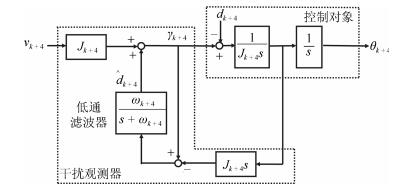
为了方便设计控制器, 采用了如图 2所示的干扰观测器(Disturbance observer, DOB)[11, 17, 36-40].
图 2中$\hat{d}_{k+4}$和$\omega_{k+4}$分别为干扰项的观测值和低通滤波器的截止频率.为了获得良好的控制性能, 该参数由试凑法可得$\omega_{k+4}=40 \rm Hz$.笔者已经验证了其在低频域可对干扰项$d_{k+4}$进行很好的补偿[11].因此, 可得:
$ \begin{align} \ddot{\theta}_{i+4}=v_{k+4}, \hspace{0.2cm}k=1, 2 \end{align} $
(6) 式中, $v_{k+4}$表示起伏子系统和旋转子系统的控制输入.
根据前述假设, 结合式(1)~(4)和式(6), 可得,
$ (m_1+m_2)l_1^2\ddot\theta_1+m_2l_1l_2\ddot\theta_3+(m_1+m_2)\times \nonumber \\ \qquad l_1L\cos\theta_{5f}\ddot\theta_5=-(m_1+m_2)l_1g\theta_1 $
(7) $ m_2l_1l_2\ddot\theta_1+m_2l_2^2\ddot\theta_3+m_2l_2 \times \nonumber \\ \qquad L\cos\theta_{5f}\ddot{\theta}_5=-m_2l_2g\theta_3 $
(8) $ \ddot\theta_5=v_5 $
(9) $(m_1+m_2)l_1^2\ddot\theta_2+m_2l_1l_2\ddot\theta_4+(m_1+m_2)\times \nonumber \\ \qquad l_1L\sin\theta_{5f}\ddot\theta_6=-(m_1+m_2)l_1g\theta_2 $
(10) $ m_2l_1l_2\ddot\theta_2+m_2l_2^2\ddot\theta_4+m_2l_2\times \nonumber \\ \qquad L\sin\theta_{5f}\ddot{\theta}_6=-m_2l_2g\theta_4 $
(11) $ \ddot\theta_6=v_6 $
(12) 其中, $\theta_{5f}$为起伏角的目标值.
式(7)~(12)写成矩阵形式可得,
$ M_1\ddot{z}_1+G_1z_1=v_5 $
(13) $ \begin{align} &M_{1}=\left[ \begin{array}{ccccccc} 1 & \dfrac{m_2l_2}{(m_1+m_2)l_1} & \dfrac{L\cos\theta_{5f}}{l_1} \\ \dfrac{l_1}{l_2} & 1 & \dfrac{L\cos\theta_{5f}}{l_2} \\ 0 & 0 & 1 \\ \end{array} \right] \nonumber \\ &G_1=\left[ \begin{array}{ccccccc} \dfrac{g}{l_1} & 0 & 0 \\ 0 & \dfrac{g}{l_2} & 0 \\ 0 & 0 & 0 \\ \end{array} \right] \nonumber \\ &\ddot{z}_{1}=\left[ \begin{array}{cccccc} \ddot{\theta}_{1} & \ddot{\theta}_{3} & \ddot{\theta}_{5} \\ \end{array} \right]^{\rm T}, z_{1}=\left[ \begin{array}{cccccc} \theta_{1} & \theta_{3} & \theta_{5} \\ \end{array} \right]^{\rm T} \nonumber \end{align} $
(14) $ \begin{align} &M_2\ddot{z}_2+G_2z_2=v_6 \\ &M_{2}=\left[ \begin{array}{ccccccc} 1 & \dfrac{m_2l_2}{(m_1+m_2)l_1} & \dfrac{L\sin\theta_{5f}}{l_1} \\ \dfrac{l_1}{l_2} & 1 & \dfrac{L\sin\theta_{5f}}{l_2} \\ 0 & 0 & 1 \\ \end{array} \right], \nonumber \\ &G_2=\left[ \begin{array}{ccccccc} \dfrac{g}{l_1} & 0 & 0 \\ 0 & \dfrac{g}{l_2} & 0 \\ 0 & 0 & 0 \\ \end{array} \right] \nonumber \\ &\ddot{z}_{2}=\left[ \begin{array}{cccccc} \ddot{\theta}_{2} & \ddot{\theta}_{4} & \ddot{\theta}_{6} \\ \end{array} \right]^{\rm T}, z_{2}=\left[ \begin{array}{cccccc} \theta_{2} & \theta_{4} & \theta_{6} \\ \end{array} \right]^{\rm T} \nonumber \end{align} $
由式(13)和式(14)可知, 起伏子系统和旋转子系统拥有非常相似的结构, 因此本文可以为其设计相似的控制器.
2. 新型滑模控制器设计和稳定性分析
2.1 含有非线性滑模面的滑模控制器设计
本节将为双摆旋转起重机设计一种新型含有非线性滑模面的滑模控制器从而同时实现旋臂高精度跟踪和摆角抑制.不同于传统的线性滑模面, 本节所提出的非线性滑模面可以使闭环系统的阻尼比从最初的较小值变化为最终的较大值.较小的阻尼比可以为系统提供较快的响应速度而较大的阻尼比则可减小超调量从而使得旋臂更加精确地跟踪给定轨迹.
基于式(13)和式(14)所示起重机线性模型, 本文所提出的非线性滑模面如下所示:
$ \begin{align} &S_k=(\Gamma_k-\Phi_kP_k)e_{1k}+\dot{e}_{1k}, \hspace{0.2cm}k=1, 2 \\ &e_{1k}=\left[ \begin{array}{cccc} \theta_{k} \\ \theta_{k+2} \\ \theta_{k+4}-\theta_{(k+4)d} \\ \end{array} \right] \nonumber \\ &\dot{e}_{1k}=\left[ \begin{array}{cccc} \dot{\theta}_{k} \\ \dot{\theta}_{k+2} \\ \dot{\theta}_{k+4}-\dot{\theta}_{(k+4)d} \\ \end{array} \right] \nonumber \end{align} $
(15) 其中, $\theta_{(k+4)d}$和$\dot{\theta}_{(k+4)d}$分别表示旋臂起伏角和旋转角的目标位移轨迹和目标速度轨迹. $P_k$是正定矩阵并满足如下所示的李雅普诺夫方程:
$ \begin{align} P_k\Gamma_k^{\rm T}+\Gamma_kP_k=-W_k, \hspace{0.2cm}k=1, 2 \end{align} $
(16) 其中, $W_k$也是正定矩阵.选取合适的满秩矩阵$\Gamma_k$使得其满足赫尔维茨定理并为闭环系统提供一个较小的初始阻尼比.非线性函数$\Phi_k$则要根据系统的输出(即, 旋臂的起伏角、旋转角以及各方向第一、二级摆角)进行选择并可用来调节闭环系统的阻尼比.虽然该函数的选取并不唯一, 但是必须满足以下两个性质:
1) 必须对于系统输出可微并保证滑动模态存在.
2) 必须从$0$变化成一个负值.
因此, 本文采用如下所示的非线性函数进行控制器的设计[36]
$ \begin{align} &\Phi_k=\left[ \begin{array}{cccc} \phi_1 & 0 & 0 \\ 0 & \phi_2 & 0 \\ 0 & 0 & \phi_3 \\ \end{array} \right] \\ &\phi_1=-\lambda_{1k}{\rm e}^{-\theta_{k}^{2}}, \phi_2=-\lambda_{2k}{\rm e}^{-\theta_{k+2}^{2}} \nonumber \\ &\phi_3=-\lambda_{3k}{\rm e}^{-(\theta_{k+4}-\theta_{(k+4)d})^{2}} \nonumber \end{align} $
(17) 式中, $\lambda_{ik}$ ($i=1, 2, 3, k=1, 2$)为正值, 而$e^{(\cdot)}$表示指数函数.
通过设计合适的控制律, 系统的所有状态量都可以进入预期的滑模面上.当处于滑模面时, 即$S_k=0$, 可得:
$ \begin{align} (\Gamma_k-\Phi_kP_k)e_{1k}+\dot{e}_{1k}=0 \end{align} $
(18) 进一步整理可得:
$ \begin{align} \dot{e}_{1k}= &-\Gamma_ke_{1k}+\Phi_kP_ke_{1k} =\nonumber\\ &(-\Gamma_k+\Phi_kP_k)e_{1k} \end{align} $
(19) 由于所设计矩阵$\Gamma_k$, $\Phi_k$和$P_k$都是可逆的, 因此上式所示系数矩阵也是可逆的, 即该矩阵是非奇异的.
为了验证所提出滑模面的稳定性, 考虑如下所示的李雅普诺夫函数:
$ \begin{align} V_{1k}=e_{1k}^{\rm T}P_ke_{1k} \end{align} $
(20) 取上式一阶时间导数, 可得:
$ \begin{align} \dot{V}_{1k}= &e_{1k}^{\rm T}P_{k}\dot{e}_{1k}+\dot{e}_{1k}^{\rm T}P_{k}e_{1k}= \nonumber\\ &e_{1k}^{\rm T}P_k(-\Gamma_k+\Phi_kP_k)e_{1k} +\nonumber \\ &e_{1k}^{\rm T}(-\Gamma_k+\Phi_kP_k)^{\rm T}P_ke_{1k} = \nonumber \\ &-e_{1k}^{\rm T}W_ke_{1k}+2U_k\Phi_k U_k^{\rm T} \end{align} $
(21) 其中, $U=e_{1k}^{\rm T}P$.因为$W_k>0$和$\Phi_k < 0$成立, 所以得证$\dot{V}_{1k} < 0$.
接下来, 基于上述所设计的非线性滑模面并采用指数趋近律, 可得:
$ \begin{align} \dot{S}_k= &\Big((\Gamma_k-\Phi_kP_k)\dot{e}_{1k}-\frac{{\rm d}\Phi_k}{{\rm d}t}P_ke_{1k}+\ddot{e}_{1k}\Big)= \nonumber \\ &-K_kS_k-Q_k{\rm sgn}(S_k) \end{align} $
(22) 其中, $K_k$和$Q_k$为系数矩阵, 并满足$K_k>0$, $Q_k>0$.
本文控制目标是实现旋臂高精度跟踪给定目标轨迹和消除两级摆角(即, $\lim_{t \to \infty}e_{1k}=0$和$\lim_{t \to \infty}\dot{e}_{1k}=0$).为此结合式(22), 可得如下控制器:
$ \begin{align} v_{k+4}= &-M_k\Big((\Gamma_k-\Phi_kP_k)\dot{e}_{1k}-\frac{{\rm d}\Phi_k}{{\rm d}t}P_ke_{1k} -\nonumber\\ &\ddot{z}_{k{\rm d}}+K_kS_k+Q_k{\rm sgn}(S_k)\Big)+G_zz_k \end{align} $
(23) 其中, . $\ddot{\theta}_{(k+4)d}$为起伏角和旋转角的目标加速度轨迹. $M_k$、$G_k$以及$z_k$ ($k=1, 2$)可参见式(13)和式(14).经验证, $M_k$是可逆矩阵.
2.2 稳定性分析
本节进行系统稳定性分析, 并考虑如下所示的李雅普诺夫函数:
$ \begin{align} V_k=\frac{1}{2}S_k^{\rm T}S_k \end{align} $
(24) 取上式一阶时间导数, 可得:
$ \begin{align} \dot{V_k}= &S_k^{\rm T}\Big((\Gamma_k-\Phi_kP_k)\dot{e}_{1k}- \frac{{\rm d}\Phi_k}{{\rm d}t}P_ke_{1k}+\ddot{e}_{1k}\Big)= \nonumber\\& S_k^{\rm T}\Big((\Gamma_k-\Phi_kP_k)\dot{e}_{1k}- \frac{{\rm d}\Phi_k}{{\rm d}t}P_ke_{1k}- \nonumber\\ &\ddot{z}_{kd}+M_k^{-1}(v_{k+4}-G_kz_k)\Big) \end{align} $
(25) 将式(23)代入式(25), 可得:
$ \begin{align} \dot{V_k}=S_k^{\rm T}\Big(-K_kS_k-Q_k{\rm sgn}(S_k)\Big) <0 \end{align} $
(26) 由于$V_k>0$, 且$\dot{V_k} < 0$, 因此可证系统是稳定的.
进一步, 设$S_k(t)$初值$S_k(0)>0$, 求解式(22)可得:
$ \begin{align} S_{k}=\Big(S_{k}(0)+\frac{Q_k}{K_k}\Big){\rm e}^{-K_kt}-\frac{Q_k}{K_k} \end{align} $
(27) 最终系统从初始状态到达滑模面($S_k=0$)所需时间为,
$ \begin{align} t=\frac{1}{K_k}\ln \Big(1+\frac{K_k|S_k(0)|}{Q_k}\Big) \end{align} $
(28) 综上, 采用如式(23)所示控制律能使变量$S_k$在有限时间内收敛到零, 并维持在零点.基于此, 则可证$\lim_{t \to \infty}e_{1k}=0$和$\lim_{t \to \infty}\dot{e}_{1k}=0$成立[41].
值得注意的是, 由于符号函数的不连续性, 式(23)所示控制器会导致系统产生抖振[33].为此, 在实际应用时采用饱和函数来替代符号函数, 则
$ \begin{align} v_{k+4}= &-M_k\Big((\Gamma_k-\Phi_kP_k)\dot{e}_{1k}- \frac{{\rm d}\Phi_k}{{\rm d}t}P_ke_{1k} \nonumber \\ &-\ddot{z}_{kd}+K_kS_k+Q_k{\rm sat}(S_k)\Big)+G_zz_k\nonumber \\ &{\rm sat}(S_k)=\left\{ \begin{array}{ll} {\rm sgn}(S_k), \hspace{0.65cm} |S_k| \geq \epsilon \\ \dfrac{S_k}{\epsilon}, \hspace{1.2cm} |S_k| < \epsilon \end{array} \right. \end{align} $
(29) 其中, $\epsilon$表示边界层的厚度且满足$\epsilon>0$.
注1. 进一步讨论新控制器对系统稳定性的影响, 将式(29)代入式(25), 可得:
$ \begin{align} \dot{V_k}=S_k^{\rm T}\Big(-K_kS_k-Q_k{\rm sat}(S_k)\Big) \end{align} $
(30) 当$|S_k| \geq \epsilon$, 则有$\dot{V}_k=S_k^{\rm T}(-K_kS_k-Q_k{\rm sgn}(S_k)) < 0$; 当$|S_k| < \epsilon$, 则有$\dot{V}_k=S_k^{\rm T}(-K_kS_k-Q_k\frac{S_k}{\epsilon}) < 0$.因此系统仍然稳定.
3. 仿真分析结果和讨论
3.1 仿真条件
从理论上讲, 阶跃信号、摆线以及输入整形曲线等均可作为旋臂的目标轨迹, 从而进行控制性能的评价.然而, 阶跃信号具有不连续性, 容易对起重机系统造成冲击, 因此在实际工程中很少直接使用.另外, 当系统参数发生变化时, 输入整形曲线往往需要进行重新设计.而摆线可以在初始点和终点处提供零加速度, 从而减轻对系统的冲击.因此, 采用如下所示的摆线作为旋臂运动的期望轨迹:
$ \begin{align} \theta_{(k+4)d}= &(\theta_{(k+4)f}-\theta_{(k+4)0}) \times\nonumber\\ & \left\{\frac{t}{t_{s}}-\frac{1}{2\pi}\sin\left(2\pi \frac{t}{t_{s}}\right)\right\}+\theta_{(k+4)0} \end{align} $
(31) 其中, $\theta_{(k+4)f}$, $\theta_{(k+4)0}$, $t_{s}$和$t_{f}$分别表示旋臂起伏角和旋转角的目标值, 初始值, 到达时间和最终时间.同时设定$\theta_{5f}=40°$, $\theta_{6f}=45°$, $\theta_{50}=\theta_{60}=0°$, $t_{s}=3$ s和$t_{f}=10$ s, 并设定当时间$t$属于区间$(t_{s}, t_{f}]$时, $\theta_{(k+4)f}=\theta_{(k+4)d}$成立.系统参数如表 1所示.而控制器参数则如表 2和表 3所示, 其中参数$\lambda_{ik}$主要影响着控制性能, 具体分析详见附录A.
表 1 起重机系统模型参数Table 1 Parameters of crane system$M_0$ (kg) $m_1$ (kg) $m_2$ (kg) $L$ (m) $l_{1}$ (m) $l_{2}$ (m) $J_5$ (kg${\rm{m}}^{2}$) $J_6$ (kg${\rm{m}}^{2}$) $g$ (m/${\rm{s}}^{2}$) 0.86 2.00 0.56 0.65 0.50 0.20 0.52 0.52 9.80 表 2 起伏子系统控制器参数Table 2 Parameters of controller in vertical subsystem$\Gamma_1$ $P_1$ $K_1$ $Q_1$ $\lambda_{i1}$ NLSS ${\rm{diag}}\{1.0, 1.0, 0.5\}$ ${\rm{diag}}\{1.0, 1.0, 1.4\}$ ${\rm{diag}}\{0.5, 0.5, 0.8\}$ ${\rm{diag}}\{1.0, 1.0, 1.5\}$ ${\rm{diag}}\{1.2, 1.5, 0.7\}$ LSS ${\rm{diag}}\{1.0, 1.0, 0.5\}$ ${\rm{diag}}\{1.0, 1.0, 1.4\}$ ${\rm{diag}}\{0.5, 0.5, 0.8\}$ ${\rm{diag}}\{1.0, 1.0, 1.5\}$ — 表 3 旋转子系统控制器参数Table 3 Parameters of controller in horizontal subsystem$\Gamma_2$ $P_2$ $K_2$ $Q_2$ $\lambda_{i2}$ NLSS ${\rm{diag}}\{1.0, 1.0, 1.5\}$ ${\rm{diag}}\{1.0, 1.0, 1.4\}$ ${\rm{diag}}\{0.5, 0.5, 0.9\}$ ${\rm{diag}}\{1.0, 1.0, 1.4\}$ ${\rm{diag}}\{1.2, 1.5, 0.8\}$ LSS ${\rm{diag}}\{1.0, 1.0, 1.5\}$ ${\rm{diag}}\{1.0, 1.0, 1.4\}$ ${\rm{diag}}\{0.5, 0.5, 0.9\}$ ${\rm{diag}}\{1.0, 1.0, 1.4\}$ — 3.2 仿真结果
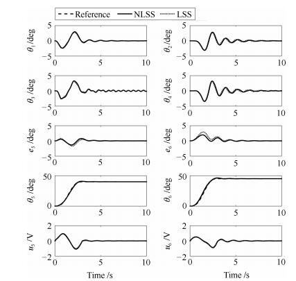
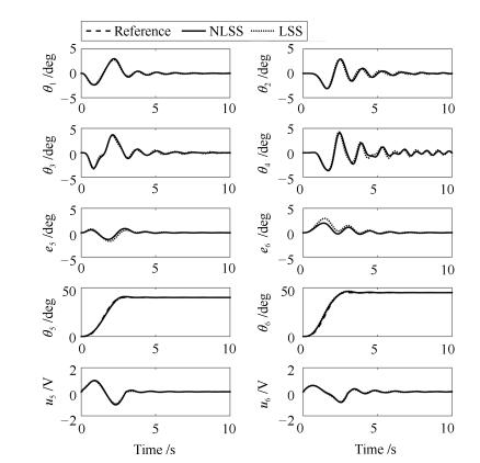
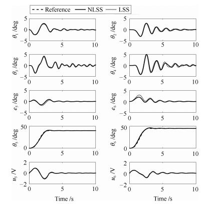
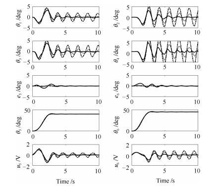
本文所提方法的仿真结果和传统线性滑模面(即$\Phi_k=0$)的结果进行比较.吊绳长度分别设定为$l_{2}=0.1$ m, $l_{2}=0.2$ m和$l_{1}=0.3$ m.对起伏角$\theta_5$、起伏角跟踪误差$e_5$、旋转角$\theta_6$、旋转角跟踪误差$e_6$、摆角$\theta_{1}$, $\theta_{3}$, $\theta_{2}$和$\theta_{4}$的仿真结果分别如图 3~5所示.
为了进行定量分析, 分别将本文所提方法和传统方法应用于旋转起重机时的最大起伏角误差$e_{5\max}$ (deg), 最大旋转角误差$e_{6\max}$ (deg), 起伏方向第一级摆角最大值$\theta_{1\max}$ (deg), 起伏方向第二级摆角最大值$\theta_{3\max}$ (deg), 旋转方向第一级摆角最大值$\theta_{2\max}$ (deg)和旋转方向第二级摆角最大值$\theta_{4\max}$ (deg)如表 4~表 6所示.由这些图与表可知, 虽然两种方法对于悬绳长度变化都具有鲁棒性, 但是使用本文所提方法可以分别减小大约$40 \%$的起伏角最大跟踪误差和$52 \%$的旋转角最大跟踪误差.另外, 对于所有的情况, 荷载摆动都得到了良好的抑制, 并且随着悬绳长度的增加摆角也逐渐增大.这些结果验证了本文所提方法既具有较好的鲁棒性还具有较好的跟踪性能, 同时不降低摆角抑制性能.
表 4 定量分析($l_2=0.1$ m)Table 4 Quantitative analysis ($l_2=0.1$ m)最大起伏角误差 最大旋转角误差 最大摆角 最大摆角 最大摆角 最大摆角 $e_{5\max}$ (deg) $e_{6\max}$ (deg) $\theta_{1\max}$ (deg) $\theta_{2\max}$ (deg) $\theta_{3\max}$ (deg) $\theta_{4\max}$ (deg) NLSS 1.21 1.91 2.91 2.75 3.15 3.21 LSS 1.68 2.91 2.77 2.81 3.11 3.18 表 5 定量分析($l_2=0.2$ m)Table 5 Quantitative analysis ($l_2=0.2$ m)最大起伏角误差 最大旋转角误差 最大摆角 最大摆角 最大摆角 最大摆角 $e_{5\max}$ (deg) $e_{6\max}$ (deg) $\theta_{1\max}$ (deg) $\theta_{2\max}$ (deg) $\theta_{3\max}$ (deg) $\theta_{4\max}$ (deg) NLSS 1.21 1.81 3.03 2.94 3.69 4.21 LSS 1.61 2.81 2.79 2.83 3.41 4.11 表 6 定量分析($l_2=0.3$ m)Table 6 Quantitative analysis ($l_2=0.3$ m)最大起伏角误差 最大旋转角误差 最大摆角 最大摆角 最大摆角 最大摆角 $e_{5\max}$ (deg) $e_{6\max}$ (deg) $\theta_{1\max}$ (deg) $\theta_{2\max} $(deg) $\theta_{3\max}$ (deg) $\theta_{4\max}$ (deg) NLSS 1.41 1.99 2.93 2.94 2.93 5.22 LSS 1.81 2.99 2.52 2.92 4.27 5.02 4. 结论
本文为了同时实现双摆旋转起重机高精度跟踪和摆角抑制, 首先, 建立含有双摆效应的起重机动力学模型, 并采用干扰观测器进行解耦线性化.其次, 基于此线性模型分别为其设计含有非线性滑模面的滑模控制器, 并通过李雅普诺夫定理分析其稳定性.通过采用本文所提方法, 无论吊绳长度$l_2=0.1$ m, $l_2=0.2$ m或者$l_2=0.3$ m, 都实现了旋臂起伏角和旋转角的跟踪和两级残留摆角的抑制.通过与传统线性滑模比较, 在不改变控制器摆角抑制性能的前提下, 起伏角和旋转角的跟踪误差分别降低了大约$40 \%$和$52 \%$.
然而, 如果起重机系统的状态量$e_{1k}$和$\dot{e}_{1k}$能够在有限时间内收敛到闭环系统的平衡点的话, 将会进一步提高起重机的运输效率.因此, 下一阶段将就此问题展开研究.
附录A. 不同非线性滑模面参数对控制性能影响分析
本节通过仿真对非线性滑模面参数选取进行分析, 并获得其对控制性能的影响.在图A示的结果中, 实线对应参数表 2中$\lambda_{ik}$值, 点线分别对应$\lambda_{11}=12$, $\lambda_{21}=15$, $\lambda_{31}=7$, $\lambda_{12}=12$, $\lambda_{22}=15$和$\lambda_{32}=8$.而点划线则对应$\lambda_{11}=120$, $\lambda_{21}=150$, $\lambda_{31}=70$, $\lambda_{12}=120$, $\lambda_{22}=150$和$\lambda_{32}=80$.由图可知, 虽然随着$\lambda_{ik}$的增大, 旋臂的定位精度会大大提高, 但是同时也降低摆角抑制性能.
-
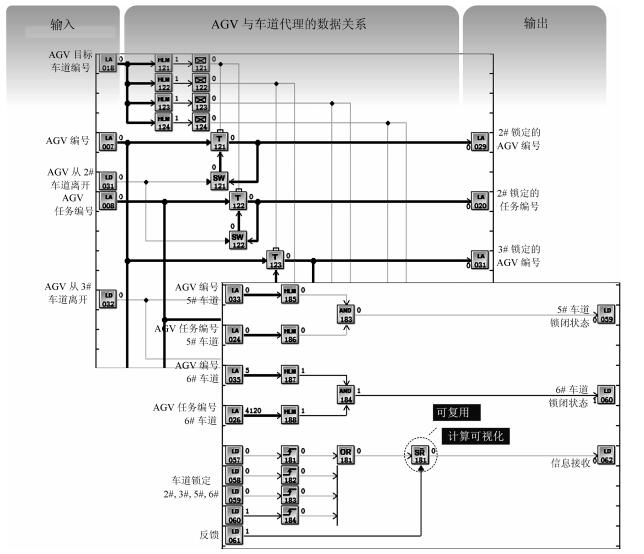
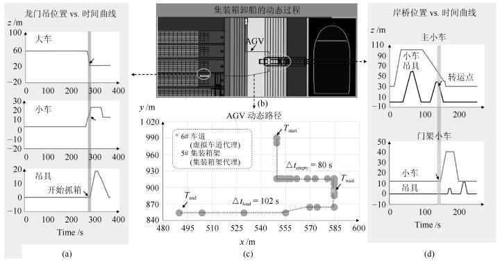
图 6 卸船模型的应用实例: AGV代理与车道代理的动态交互
Fig. 6 An application example of the discharge model: The dynamic interaction among AGV agents and lane agents
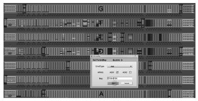
图 12 平行码头中人机交互系统工程应用实例
Fig. 12 An application example of PCTICS human-computer interaction system
表 1 不同行驶策略下AGV的任务时耗(s) $^{1}$
Table 1 The time cost of AGV task under different driving strategies (s) $^{1}$
$T_{\rm mode 1}$ $T'_{\rm mode 1}$ $T_{\rm mode 2}$ $T'_{\rm mode 2}$ (Task 1) (Task 2) (Task 1) (Task 2) 251 316 243 328 267 320 245 315 284 330 253 301 256 349 254 322 257 328 253 327 432 334 260 320 526 328 261 457 468 304 248 533 318 323 265 450 241 323 276 322 $^{1}$Task 1表示从104号岸桥搬运10个集装箱至47号堆场, Task 2表示从105号岸桥搬运10个集装箱至49号堆场; $T_{\rm mode 1}$和$T'_{\rm mode 1}$分别表示无汇流行驶策略下AGV完成任务1和任务2的时耗; $T_{\rm mode 2}$和$T'_{\rm mode 2}$分别表示汇流行驶策略下AGV完成任务1和任务2的时耗.  下载: 导出CSV
-
[1] Steenken D, Voß S, Stahlbock R. Container terminal operation and operations research-a classification and literature review. OR Spectrum, 2004, 26(1):3-49 doi: 10.1007/s00291-003-0157-z [2] Liu C I, Jula H, Ioannou P A. Design, simulation, and evaluation of automated container terminals. IEEE Transactions on Intelligent Transportation Systems, 2002, 3(1):12-26 doi: 10.1109/6979.994792 [3] Kim K H, Phan M H T, Woo Y J. New conceptual handling systems in container terminals. Industrial Engineering & Management Systems, 2012, 11(4):299-309 http://cn.bing.com/academic/profile?id=f6b73cd7114f43a5dd80468a9a00ca87&encoded=0&v=paper_preview&mkt=zh-cn [4] Dkhil H, Yassine A, Chabchoub H. Optimization of container handling systems in automated maritime terminal. In:Advanced Methods for Computational Collective Intelligence. Studies in Computational Intelligence, vol 457. Berlin, Heidelberg:Springer, 2013. 301-312 https://www.researchgate.net/publication/287785081_Optimization_of_Container_Handling_Systems_in_Automated_Maritime_Terminal [5] Jin J G, Lee D H, Hu H. Tactical berth and yard template design at container transshipment terminals:a column generation based approach. Transportation Research, Part E:Logistics and Transportation Review, 2015, 73:168-184 doi: 10.1016/j.tre.2014.11.009 [6] 王飞跃.平行系统方法与复杂系统的管理和控制.控制与决策, 2004, 19(5):485-489, 514 doi: 10.3321/j.issn:1001-0920.2004.05.002Wang Fei-Yue. Parallel system methods for management and control of complex systems. Control & Decision, 2004, 19(5):485-489, 514 doi: 10.3321/j.issn:1001-0920.2004.05.002 [7] 王飞跃, 刘德荣, 熊刚, 程长建, 赵冬斌.复杂系统的平行控制理论及应用.复杂系统与复杂科学, 2012, 9(3):1-12 http://d.old.wanfangdata.com.cn/Periodical/fzxtyfzxkx201203001Wang Fei-Yue, Liu De-Rong, Xiong Gang, Cheng Chang-Jian, Zhao Dong-Bin. Parallel control theory of complex systems and applications. Complex Systems and Complexity Science, 2012, 9(3):1-12 http://d.old.wanfangdata.com.cn/Periodical/fzxtyfzxkx201203001 [8] 王飞跃.平行控制:数据驱动的计算控制方法.自动化学报, 2013, 39(4):293-302 http://www.aas.net.cn/CN/abstract/abstract17915.shtmlWang Fei-Yue. Parallel control:a method for data-driven and computational control. Acta Automatica Sinica, 2013, 39(4):293-302 http://www.aas.net.cn/CN/abstract/abstract17915.shtml [9] Stula M, Stipanicev D, Maras J. Distributed computation multi-agent system. New Generation Computing, 2013, 31(3):187-209 doi: 10.1007/s00354-012-303-8 [10] Frees S. Context-driven interaction in immersive virtual environments. Virtual Reality, 2010, 14(4):277-290 doi: 10.1007/s10055-010-0178-2 [11] Carlo H J, Vis I F A, Roodbergen K J. Storage yard operations in container terminals:literature overview, trends, and research directions. European Journal of Operational Research, 2014, 235(2):412-430 doi: 10.1016/j.ejor.2013.10.054 [12] Liu Q W. Efficiency Analysis of Container Ports and Terminals[Ph.D. dissertation], University College London, London, 2010 [13] Zhen L, Jiang X J, Lee L H, Chew E P. A review on yard management in container terminals. Industrial Engineering & Management Systems, 2013, 12(4):289-304 http://cn.bing.com/academic/profile?id=db4bc6d3ddf5f290c546ba23e391b546&encoded=0&v=paper_preview&mkt=zh-cn [14] Tao J H, Qiu Y Z. A simulation optimization method for vehicles dispatching among multiple container terminals. Expert Systems with Applications, 2015, 42(7):3742-3750 doi: 10.1016/j.eswa.2014.12.041 [15] Vacca I, Salani M, Bierlaire M. Optimization of operations in container terminals:hierarchical vs integrated approaches. In:Proceedings of the 10th SWISS Transport Research Conference. Switzerland, 2010. [16] Cai B H, Huang S D, Liu D K, Yuan S, Dissanayake G, Lau H, et al. Multiobjective optimization for autonomous straddle carrier scheduling at automated container terminals. IEEE Transactions on Automation Science & Engineering, 2013, 10(3):711-725 http://www.wanfangdata.com.cn/details/detail.do?_type=perio&id=a6dafcbdcf9938869e13a2579ba59c26 [17] Lau H Y K, Zhao Y. Integrated scheduling of handling equipment at automated container terminals. International Journal of Production Economics, 2008, 112(2):665-682 doi: 10.1016/j.ijpe.2007.05.015 [18] Yang Y C. Operating strategies of CO2 reduction for a container terminal based on carbon footprint perspective. Journal of Cleaner Production, 2017, 141:472-480 doi: 10.1016/j.jclepro.2016.09.132 [19] Yun W Y, Choi Y S. A simulation model for container-terminal operation analysis using an object-oriented approach. International Journal of Production Economics, 1999, 59(1-3):221-230 doi: 10.1016/S0925-5273(98)00213-8 [20] Dulebenets M A. Application of evolutionary computation for berth scheduling at marine container terminals:parameter tuning versus parameter control. IEEE Transactions on Intelligent Transportation Systems, 2018, 19(1):25-37 doi: 10.1109/TITS.2017.2688132 [21] Speer U, Fischer K. Scheduling of different automated yard crane systems at container terminals. Transportation Science, 2017, 51(1):305-324 doi: 10.1287/trsc.2016.0687 [22] Al-Dhaheri N, Jebali A, Diabat A. A simulation-based Genetic Algorithm approach for the quay crane scheduling under uncertainty. Simulation Modelling Practice & Theory, 2016, 66:122-138 http://www.wanfangdata.com.cn/details/detail.do?_type=perio&id=5295b68b0d3df361df4c9690cd2811dc [23] Tang G L, Wang W Y, Song X Q, Guo Z J, Yu X H, Qiao F F. Effect of entrance channel dimensions on berth occupancy of container terminals. Ocean Engineering, 2016, 117:174-187 doi: 10.1016/j.oceaneng.2016.03.047 [24] Dkhil H, Yassine A, Chabchoub H. Multi-objective optimization of the integrated problem of location assignment and straddle carrier scheduling in maritime container terminal at import. Journal of the Operational Research Society, to be published doi: 10.1057%2Fs41274-017-0184-9 [25] Gharehgozli A H, Vernooij F G, Zaerpour N. A simulation study of the performance of twin automated stacking cranes at a seaport container terminal. European Journal of Operational Research, 2017, 261(1):108-128 doi: 10.1016/j.ejor.2017.01.037 [26] Liang C J, Fan L B, Xu D H, Ding Y, Gen M. Research on coupling scheduling of quay crane dispatch and configuration in the container terminal. Computers & Industrial Engineering, 2018, 125:649-657 http://cn.bing.com/academic/profile?id=314f6fc5b2995f21b6c55af5790f0ae7&encoded=0&v=paper_preview&mkt=zh-cn [27] Xin J B, Negenborn R R, Lodewijks G. Rescheduling of interacting machines in automated container terminals. In:Proceedings of the 19th World Congress the International Federation of Automatic Control. Cape Town, South Africa:IFAC, 2014. 1698-1704 [28] Homayouni S M, Tang S H, Motlagh O. A genetic algorithm for optimization of integrated scheduling of cranes, vehicles, and storage platforms at automated container terminals. Journal of Computational & Applied Mathematics, 2014, 270:545-556 http://www.wanfangdata.com.cn/details/detail.do?_type=perio&id=6d82689959e2463ebd9ab637310393b0 [29] Yang X M, Mi W J, Li X, An G L, Zhao N, Mi C. A simulation study on the design of a novel automated container terminal. IEEE Transactions on Intelligent Transportation Systems, 2015, 16(5):2889-2899 doi: 10.1109/TITS.2015.2425547 [30] Kim K H, Won S H, Lim J K, Takahashi T. An architectural design of control software for automated container terminals. Computers & Industrial Engineering, 2004, 46(4):741-754 http://www.wanfangdata.com.cn/details/detail.do?_type=perio&id=ca2f4c69c9f6a74d857be61799464fd5 [31] Xin J B, Negenborn R R, Lodewijks G. Energy-aware control for automated container terminals using integrated flow shop scheduling and optimal control. Transportation Research, Part C:Emerging Technologies, 2014, 44:214-230 doi: 10.1016/j.trc.2014.03.014 [32] Thurston T, Hu H S. Distributed agent architecture for port automation. In:Proceedings of the 26th Annual International Computer Software and Applications. Oxford, UK:IEEE, 2002. 81-87 [33] Li L, Wang X D. Modeling and simulation of container terminal logistics system. In:Proceedings of the 2009 Second International Workshop on Knowledge Discovery and Data Mining. Moscow, Russia:IEEE, 2009. 729-732 [34] Rebollo M, Julián V, Carrascosa C, Botti V. A multi-agent system for the automation of a port container terminal. In:Proceedings of Autonomous Agents 2000 Workshop on Agents in Industry. 2000. https://www.researchgate.net/publication/2896616_A_Multi-Agent_System_for_the_Automation_of_a_Port [35] 王祥雪, 朱瑾.基于MAS的集装箱自动化码头协同作业系统模型.计算机应用研究, 2013, 30(4):1072-1075 doi: 10.3969/j.issn.1001-3695.2013.04.030Wang Xiang-Xue, Zhu Jin. Multi-agent system based collaborative operation system about ZPMC automatic container terminal. Application Research of Computers, 2013, 30(4):1072-1075 doi: 10.3969/j.issn.1001-3695.2013.04.030 [36] Haramabadi H R. Dynamic Scheduling of Automated Guided Vehicles in Container Terminals[Ph.D. dissertation], University of Essex, England, 2006 [37] Choi H R, Kim H S, Park B J, Park N K, Lee S W. An ERP approach for container terminal operating systems. Maritime Policy & Management, 2003, 30(3):197-210 http://cn.bing.com/academic/profile?id=9ec0583adeeb1d4d129c5b77e6c0e94c&encoded=0&v=paper_preview&mkt=zh-cn [38] Hoshino S, Fujisawa T, Maruyama S, Hino H, Ota J. Double container-handling operation for an efficient seaport terminal system. Intelligent Autonomous Systems, 2008, 10:173-182 [39] 李斌, 杨家其. PID控制框架下的集装箱码头调度算法.交通运输系统工程与信息, 2014, 14(1):124-130 doi: 10.3969/j.issn.1009-6744.2014.01.020Li Bin, Yang Jia-Qi. A scheduling algorithm for container terminals within PID control framework. Journal of Transportation Systems Engineering & Information Technology, 2014, 14(1):124-130 doi: 10.3969/j.issn.1009-6744.2014.01.020 [40] Dragović B, Tzannatos E, Park N K. Simulation modelling in ports and container terminals:literature overview and analysis by research field, application area and tool. Flexible Services & Manufacturing Journal, 2017, 29(1):4-34 http://cn.bing.com/academic/profile?id=51b2621a1a4499ff735a8b4c06e1075f&encoded=0&v=paper_preview&mkt=zh-cn [41] 郑松, 倪维斗.基于数据引擎技术的通用控制站.电气时代, 2008, (9):122-125 doi: 10.3969/j.issn.1000-453X.2008.09.034Zheng Song, Ni Wei-Dou. Data engine based universal controller. Electric Age, 2008, (9):122-125 doi: 10.3969/j.issn.1000-453X.2008.09.034 [42] 王飞跃.软件定义的系统与知识自动化:从牛顿到默顿的平行升华.自动化学报, 2015, 41(1):1-8 doi: 10.3969/j.issn.1003-8930.2015.01.001Wang Fei-Yue. Software-defined systems and knowledge automation:a parallel paradigm shift from Newton to Merton. Acta Automatica Sinica, 2015, 41(1):1-8 doi: 10.3969/j.issn.1003-8930.2015.01.001 [43] 王坤峰, 苟超, 王飞跃.平行视觉:基于ACP的智能视觉计算方法.自动化学报, 2016, 42(10):1490-1500 http://www.aas.net.cn/CN/abstract/abstract18936.shtmlWang Kun-Feng, Gou Chao, Wang Fei-Yue. Parallel vision:an ACP-based approach to intelligent vision computing. Acta Automatica Sinica, 2016, 42(10):1490-1500 http://www.aas.net.cn/CN/abstract/abstract18936.shtml [44] 王飞跃.关于复杂系统研究的计算理论与方法.中国基础科学, 2004, 6(5):3-10 doi: 10.3969/j.issn.1009-2412.2004.05.001Wang Fei-Yue. Computational theory and method on complex system. China Basic Science, 2004, 6(5):3-10 doi: 10.3969/j.issn.1009-2412.2004.05.001 [45] 郑松, 倪维斗.分布式控制系统动态重构技术研究与实现.原子能科学技术, 2009, 43(8):724-729 http://d.old.wanfangdata.com.cn/Periodical/yznkxjs200908011Zheng Song, Ni Wei-Dou. Research and implementation of dynamic reconfiguration technology in distributed control system. Atomic Energy Science & Technology, 2009, 43(8):724-729 http://d.old.wanfangdata.com.cn/Periodical/yznkxjs200908011 [46] Zheng S, Zhang Q, Zheng R, Huang B Q, Song Y L, Chen X C. Combining a multi-agent system and communication middleware for smart home control:a universal control platform architecture. Sensors, 2017, 17(9):2135 doi: 10.3390/s17092135 [47] 刘烁, 王帅, 孟庆振, 叶佩军, 王涛, 黄文林, 王飞跃.基于ACP行为动力学的犯罪主体行为平行建模分析.自动化学报, 2018, 44(2):251-261 http://www.aas.net.cn/CN/abstract/abstract19220.shtmlLiu Shuo, Wang Shuai, Meng Qing-Zhen, Ye Pei-Jun, Wang Tao, Huang Wen-Lin, Wang Fei-Yue. Parallel modeling of criminal subjects behavior based on ACP behavioral dynamics. Acta Automatica Sinica, 2018, 44(2):251-261 http://www.aas.net.cn/CN/abstract/abstract19220.shtml [48] Chen D W, Yin J T, Chen L, Xu H Z. Parallel control and management for high-speed maglev systems. IEEE Transactions on Intelligent Transportation Systems, 2017, 18(2):431-440 doi: 10.1109/TITS.2016.2577037 [49] 吴沙坪, 何继红, 罗勋杰.洋山四期自动化集装箱码头装卸工艺设计.水运工程, 2016, (9):159-162, 166 doi: 10.3969/j.issn.1002-4972.2016.09.033Wu Sha-Ping, He Ji-Hong, Luo Xun-Jie. Handling technology design for automated container terminal of Yangshan deepwater port phase Ⅳ project. Port & Waterway Engineering, 2016, (9):159-162, 166 doi: 10.3969/j.issn.1002-4972.2016.09.033 [50] 刘广红, 程泽坤, 罗勋杰, 庄骅, 何继红.洋山四期工程全自动化集装箱码头总体布置.水运工程, 2016, (9):46-51 doi: 10.3969/j.issn.1002-4972.2016.09.010Liu Guang-Hong, Cheng Ze-Kun, Luo Xun-Jie, Zhuang Hua, He Ji-Hong. General layout of fully automated container terminal in phase Ⅳ of Yangshan project. Port & Waterway Engineering, 2016, (9):46-51 doi: 10.3969/j.issn.1002-4972.2016.09.010 [51] 程泽坤, 刘广红, 何继红.洋山港四期全自动化集装箱码头总体布置创新.中国港湾建设, 2016, 36(10):1-7 doi: 10.7640/zggwjs201610001Cheng Ze-Kun, Liu Guang-Hong, He Ji-Hong. Innovation on general layout of fully-automated container terminal in Yangshan Port phase Ⅳ project. China Harbour Engineering, 2016, 36(10):1-7 doi: 10.7640/zggwjs201610001 [52] Li D L, Niu K. Dijkstra's algorithm in AGV. In:Proceedings of the 9th IEEE Conference on Industrial Electronics and Applications. Hangzhou, China:IEEE, 2014. 1867-1871 [53] Gayathri N, Chandrakala K R M V. A novel technique for optimal vehicle routing. In:Proceedings of the 2014 International Conference on Electronics and Communication Systems. Coimbatore, India:IEEE, 2014. 1-5 -


 下载:
下载:


计量
- 文章访问数: 2506
- HTML全文浏览量: 555
- PDF下载量: 730
- 被引次数: 0
