

-
摘要: 对于串联弹性驱动器(Series elastic actuator,SEA)而言,已有方法大都将其弹性组件视为线性弹簧.然而为了追求更高的能量密度,SEA的机械结构越来越复杂,使其控制问题更具挑战性;此外,现有方法均未考虑当SEA应用于交互系统中,其负载端动力学模型会产生剧烈变化的情况.针对这些问题,本文设计了一种面向交互应用的自适应滑模控制方法.具体而言,首先在考虑了非线性SEA输出特性及系统中可能存在的扰动的情况下,描述了SEA系统的动力学方程,并对其进行了分析和变换.在此基础上设计了负载运动观测器和自适应滑模控制器,使得本文方法能够在负载端动力学模型完全未知的情况下完成SEA的力矩控制.最后通过引入辅助系统,对输入饱和的情况进行了有效的处理.通过理论分析证明了闭环控制系统的稳定性及信号有界性,随后的仿真与实验结果也表明了这种自适应滑模控制器良好的控制性能和对不确定性因素的鲁棒性.Abstract: For series elastic actuator (SEA) systems, most existing methods treat the mechanical component as a linear spring. However, in order to achieve high energy density, mechanical structures of SEAs are becoming more and more complex, which makes the control problem more challenging. Additionally, currently available approaches cannot guarantee the control performance when the payload dynamics changes drastically during the interaction process. To deal with these problems, an adaptive sliding-mode control method is proposed for interaction applications. Specifically, by taking account of nonlinear SEAs and disturbances, the dynamics of SEA systems is uniformly described and transformed. Then, an observer and adaptive sliding mode controller are designed and they work well even in the presence of unknown payload dynamics. Finally, an auxiliary system is designed to deal with the saturation problem. Stability and boundedness of the closed-loop signal is ensured mathematically. Subsequent experiment results also demonstrate that the designed controller is robust against system uncertainties and can achieve a superior performance for SEA torque control.
-
串联弹性驱动器(Series elastic actuator, SEA)[1]是将弹性组件串联于传统驱动源(伺服电机、液压等)与负载间的驱动装置.弹性组件的引入为SEA带来了本质安全、低阻抗、力/力矩输出精度高等优点, 使得SEA作为理想力/力矩源被广泛应用于人-机交互系统中, 提高了人-机交互的安全性和舒适性[2-5].
SEA最先于1995年由MIT的研究者Pratt G. A.提出并实现, 近20年来, 国内外相关研究人员针对SEA的力/力矩控制问题展开了大量研究.具体而言, Pratt等[1]提出了比例-积分-微分(Proportion-integration-differentiation, PID)结合前馈补偿的控制策略; 随后, Pratt等[6]又提出了级联PID控制策略, 其中力矩控制环作为外环, 电机位置环作为内环; 之后, 许多研究人员对该方法进行了改进和拓展, Wyeth[7]提出了用电机速度环代替电机位置环作为控制内环的控制策略, 并进行了相关的理论分析和实验验证; Vallery等[8]结合无源控制理论对级联PID控制方法的参数选取进行了更深入的研究; Tagliamonte等[9]将阻抗控制理论引入到级联PID控制方法中, 来优化控制系统在交互应用中的性能.由于级联PID控制器结构简单, 便于应用, 使得其被广泛地应用于SEA系统中[10-13].为了进一步提高控制系统的鲁棒性, Kong等[14-15]提出了一系列基于线性扰动观测器(Linear disturbance observer, LDOB)的控制方法.为了能够在线适应人-机交互中人的动态特性, Calanca等[16]提出了一种基于参考模型的自适应控制方法.除此之外, 一系列控制方法, 如滑模控制方法[17]、基于内部补偿器的控制方法[18]、$H_2$鲁棒控制方法[19]、基于神经网络的控制方法[20]、基于快速收敛的李雅普诺夫函数的控制方法[21-22]等都被用来解决SEA的力/力矩控制问题, 并取得了不错的效果.
值得指出的是, 包括上述列举的文献在内, 已有的绝大多数控制方法都是针对线性SEA系统设计的(SEA输出力矩与电机端和负载端的相对转角呈线性关系).然而, 随着SEA的发展, 为了追求更高的能量密度和更好的仿生特性, 其机械结构变得日趋复杂, 促使非线性SEA的出现(力/力矩输出与电机和负载的相对转角呈现非线性关系)[23-25].显然, 非线性SEA的力/力矩控制问题更具有挑战性, 目前该方面的论文相对较少.文献[26-27]应用级联PID控制方法来控制非线性SEA, 对于复杂模型来说, PID控制是一种简单有效的控制方法, 但该方法在理论上难以做进一步的分析; 文献[28-29]提出了一种线性化的方法, 将描述SEA力矩输出特性的非线性函数进行局部线性化后, 利用线性系统理论分别设计LDOB和控制器使系统稳定, 相应的, 该控制方法最大的不足在于只能确保系统的局部稳定性; 文献[30-31]分别针对投掷和敲击任务, 提出了基于最优控制理论的控制方法, 但是该类方法在分析过程中假定负载端的动力学模型已知, 无法应对在交互应用中负载端动力学模型剧烈变化的情况; 文献[32-33]提出了一类基于延时估计的控制方法, 但该方法只能保证控制误差全局一致最终有界(Globally, uniformly, ultimately bounded, GUUB).在我们之前的研究中[34], 提出过一种基于非线性扰动观测器(Nonlinear disturbance observer, NDOB)的滑模控制方法, 但该方法对SEA动力学建模中可能存在的内外扰动缺乏分析.值得一提的是, 除最优控制外, 以上控制方法在控制器设计时均未考虑输入饱和的情况, 而该情形在实际应用中是无法避免的.
基于上述问题, 本文提出了一种自适应滑模控制方法.具体而言, 首先构建了更一般的单关节SEA机器人系统动力学模型, 并对其进行了分析和变换; 在此基础上, 设计了运动观测器来观测负载端的运动信号; 其次, 结合负载运动观测器设计了一种自适应滑模控制律, 并引入了抗饱和环节, 进而形成了一种抗饱和控制律.本文通过Lyapunov方法对控制器的稳定性及闭环系统中信号的有界性进行了严格的数学分析.最后, 进行了仿真和实验验证, 并与已有控制方法进行了对比.结果表明本文设计的自适应滑模控制器能够取得更好的控制效果, 且具有很强的鲁棒性.
本文的其他部分组织如下:第1节通过对SEA动力学模型进行分析和变换, 对其控制问题进行了详尽的描述; 第2节设计了负载运动观测器和带有抗饱和环节的自适应滑模控制器, 并对闭环系统的稳定性和信号有界性进行了理论分析; 第3节给出了仿真和实验结果; 最后一节是对本文工作的总结和展望.
1. 问题描述
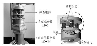
本文主要的研究对象是如图 1所示的非线性旋转型SEA.该SEA主要由伺服电机(配有谐波减速器)和弹性组件两部分组成, 弹性组件的机械结构参考了文献[23]的设计.该串联弹性驱动器的柔性主要来源为三个模具压簧, 其力矩输出过程分析如下:当电机与负载发生相对转动时, 滚轮会沿圆弧轨道运动, 进而压缩三个压簧.压簧的压缩会对滚轮产生沿电机轴向且指向电机方向的压力, 与此同时, 圆弧轨道会对滚轮提供一定的支持力, 该支持力可以沿电机轴向和垂直于电机轴向两个方向分解.其中, 在忽略滚轮重力的情况下, 沿电机轴向方向上的分力与弹簧的压缩力大小相等, 方向反向; 垂直于电机轴向方向的分力提供该SEA的输出力矩.根据图 1, 该SEA系统的力矩输出推导过程如下:
$\sin \theta = \frac{{c\varphi }}{{R - r}}$
(1) $\Delta y = (R - r)(1 - \cos \theta )$
(2) $F = 3{k_s}\Delta y$
(3) ${\tau _{{\rm{SEA}}}} = 3{k_s}c(R - r)(\tan \theta - \sin \theta )$
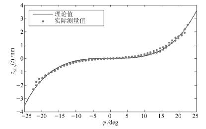
(4) 式中, $\varphi$代表电机和负载的相对转角; $\theta$表示滚轮在圆弧轨道上滚动的角度; R, r分别表示圆弧轨道和滚轮的半径; $\Delta y$表示压簧的压缩量; F表示三个压簧共产生的合力; $\tau_{\rm SEA}$为SEA的输出力矩.该SEA的相关机械参数如表 1所示. SEA的机械参数辨识参见文献[35], 利用辨识所得的参数进行模型验证实验, 其结果如图 2所示, 实际测量值利用力矩传感器直接测得.通过实验结果可以看出, 虽然由于阻尼、传感器延时等不确定因素导致了迟滞现象的出现, 但理论值与实际测量值的偏差在$\pm0.3$ Nm之内, 说明了式(1) ~ (4) 的有效性.通过模型验证, 可以将该SEA的一个重要性质归纳如下:
表 1 SEA机械参数Table 1 The mechanical parameters of the SEAParameter Value Ks 13 600 N/m c 0.018 m R 0.020 m r 0.005 m 性质1. SEA的输出力矩$\tau_{\rm SEA}$与电机和负载端的相对转角$\varphi$间呈连续的一一映射关系, 即$\tau_{\rm SEA}=f(\varphi)$, $f(\varphi)$为关于$\varphi$的连续可逆函数.且$f(\varphi)\in {\bf C}^2$.
将非线性SEA应用于单关节SEA交互机器人系统, 其示意图如图 3所示, 该机器人系统的动力学方程可描述如下:
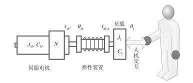 图 3 单关节SEA交互机器人示意图Fig. 3 Schematic representation of the single SEA interaction robot system
$\left\{ \begin{array}{l} {\tau _M} = {J_M}{{\ddot \theta }_M} + {c_M}{{\dot \theta }_M} + {\tau _{{\rm{SEA}}}} + {d_M}\\ {\tau _{{\rm{SEA}}}} = f(\varphi ) = {J_L}({\theta _L}){{\ddot \theta }_L} + {C_L}({{\dot \theta }_L},{\theta _L}) + {d_L}\\ \varphi = {\theta _M} - {\theta _L} \end{array} \right.$
(5) 式(1) 中, $J_M$、$c_M$分别代表电机(将减速器和电机组成的驱动源整体简称为电机)的转动惯量和阻尼系数; $J_L(\theta_L)$代表负载的惯量; $C_L(\dot{ \theta }_L, \theta_L)$包括负载端的科氏力、重力等因素; $\theta_M(t)$代表电机端的转动角度; $\theta_L(t)$代表负载端的转动角度; $d_M(t)$、$d_L(t)$分别代表电机端和负载端可能存在的扰动, 包括模型误差、外界交互力等因素; $\tau_M(t)$表示电机的输出力矩; $\tau_{\rm SEA}(t)$代表SEA的输出力矩; $\varphi(t)$代表电机端与负载端的相对转角; $f(\varphi)$为描述SEA输出力矩与电机和负载间相对转角的函数.在这里值得指出的是, 区别于传统的线性SEA系统, $f(\varphi)$被视为一类更广义的函数.
基于性质1, SEA力矩控制问题可以转化为电机与负载端的相对位置控制问题, 即可得到如下控制目标的等价关系:
$\varphi (t) \to {\varphi _d}(t) \Leftrightarrow {\tau _{{\rm{SEA}}}}(t) \to {\tau _{{\rm{SEA}},d}}(t)$
(6) 其中, $\tau_{{\rm SEA}, d}(t)$表示SEA力矩参考轨迹, $\varphi_d(t)$表示电机与负载间相对转角的参考轨迹, $\tau_{{\rm SEA}, d}(t)$和$\varphi_d(t)$通过映射关系$f(\varphi)$ ($f^{(-1) }(\tau_{\rm SEA})$)可以相互转化, 考虑到驱动器的物理约束及跟踪力矩轨迹的平滑性, 期望轨迹$\tau_{{\rm SEA}, d}(t)$ ($\varphi_d(t)$)应足够平滑: $\tau_{{\rm SEA}, d}(t)\in{\bf C}^2$ ($\varphi_d(t)\in{\bf C}^2$).
通常情况下, 在交互应用中负载端的动力学模型往往完全未知且会发生剧烈的变化[2-5], 为了使控制器能够很好地处理这种情形, 在不考虑负载端动力学模型的情况下, 定义辅助变量如下: $x_1(t)=\varphi(t)$
${x_2}(t) = {{\dot \theta }_M}(t) = {{\dot x}_1}(t) + {{\dot \theta }_L}(t)$
将SEA动力学方程(5) 整理成如下形式:
$\left\{ \begin{array}{l} {{\dot x}_1} = {x_2} - {{\dot \theta }_L}\\ {J_M}{{\dot x}_2} = {\tau _M} - f({x_1}) - {c_M}{x_2} - {d_M}\\ y = {x_1} \end{array} \right.$
(7) 至此, 可以将SEA力矩控制问题描述为:针对系统(7) 设计控制器$\tau_M(t)$, 使得$\lim_{t\rightarrow\infty} x_1(t)=x_{1, d}(t)$.
为了后续的控制器分析, 考虑到实际情况和物理约束, 在缺乏电机端扰动和负载端动力学模型先验知识的前提下, 我们作出以下假设.
假设1. 负载运动速度$|\dot {\theta}_L|$, 加速度$|\ddot {\theta}_L|$, 加加速度$|\dddot {\theta}_L|$有上界, 即$|\dot {\theta}_L|, |\ddot {\theta}_L|, |\dddot {\theta}_L|\in\mathcal{L}_{\infty}$.
假设2. 扰动$|d_M(t)|$有上界, 即$|d_M(t)|\in\mathcal{L}_{\infty}$.
2. 控制器设计与分析
对于SEA交互系统的力矩控制而言, 主要考虑如下两个要求: 1) 要快速精确地达到期望力矩值/轨迹; 2) SEA系统往往需要与外界进行频繁的交互, 因此要求控制器对负载变化和外界扰动具有很强的鲁棒性, 使得系统在面对不同的交互情景下都能够正常工作.本文接下来所设计的自适应滑模控制器可实现以上目标.具体而言, 首先, 设计了负载运动观测器来观测负载的运动情况; 其次, 构建了滑模面并设计了自适应滑模控制器来引导系统状态收敛于滑模面; 最后, 在控制器中引入了抗饱和环节, 使得控制器满足输入饱和约束.借助Lyapunov方法和芭芭拉定理对闭环系统的稳定性和有界性进行了理论分析.
2.1 负载运动观测器设计(Payload observer)
根据上一节的描述可以知道, 控制目标是使电机和负载的相对转角达到期望值或期望轨迹, 为了实现这一目标, 需要将负载端的运动信号加入到反馈通道中, 在不考虑负载端的动力学模型的前提下, 就有必要构造运动观测器对负载的运动进行详尽的观测, 根据式(3), 设计观测器[36-38]如下:
$\left\{ \begin{array}{*{35}{l}} {{{\hat{\dot{\theta }}}}_{L}}={{z}_{1}}-{{l}_{1}}{{x}_{1}} \\ {{{\dot{z}}}_{1}}={{l}_{1}}({{x}_{2}}-{{{\hat{\dot{\theta }}}}_{L}})+{{{\hat{\ddot{\theta }}}}_{L}} \\ {{{\hat{\ddot{\theta }}}}_{L}}={{z}_{2}}-{{l}_{2}}{{x}_{1}} \\ {{{\dot{z}}}_{2}}={{l}_{2}}({{x}_{2}}-{{{\hat{\dot{\theta }}}}_{L}}) \\ \end{array} \right.$
(8) 其中, $l_1, l_2\in\mathbf{R}^+$为观测增益; $\hat {\dot \theta}_L, \hat {\ddot \theta}_L$为负载速度和加速度的观测信号; $z_1, z_2$为辅助变量.
定理1. 在假设2的前提下, 本文所设计的运动观测器(8) 可实现对负载速度$\dot \theta_L$和加速度$\ddot \theta_L$的有效观测, 即观测误差$e_d=[\dot \theta_L-\hat {\dot \theta}_L \quad \ddot \theta_L-\hat {\ddot \theta}_L]^{\rm T}$有界.
证明. 对$e_d(t)$求导并将式(7) 和(8) 代入整理可得:
$\begin{gathered} {{\dot e}_d} = A{e_d} + B{{\dddot \theta }_L} \hfill \\ A = \left[ {\begin{array}{*{20}{c}} { - {l_1}}&{\quad 1} \\ { - {l_2}}&{\quad 0} \end{array}} \right] \hfill \\ B = {\left[ {\begin{array}{*{20}{c}} 0&{\quad 1} \end{array}} \right]^{\text{T}}} \hfill \\ \end{gathered} $
(9) 基于假设1的条件$|\dddot {\theta_L}|\in\mathcal{L}_{\infty}$, 通过线性理论分析[39]可知, 通过选取增益$l_1, l_2$使得方程$s^2+l_1s+l_2=0$的根具有负实部, 即可保证观测误差$e_d(t)$有界.
2.2 自适应滑模控制器设计(Adaptive sliding-mode controller design)
首先定义误差变量$e_1=x_1-x_{1, d}=\varphi-\varphi_d$, 定义线性滤波器$r=\dot e_1+ \lambda e_1$, 其中$\lambda \in\mathbf{R}^+ $.基于定理1的结论和假设2的条件, 在此定义一正常数$D\in\mathbf{R}^+$满足$|d_M+J_M\tilde {\ddot \theta}_L|\leq D$, 其中$\tilde {\ddot \theta}_L=\ddot {\theta}_L-\hat {\ddot \theta}_L$为加速度观测误差.
结合上述定义变量, 设计自适应滑模控制器如下:
$\begin{align} & {{\tau }_{M}}=f({{x}_{1}})+{{{\hat{c}}}_{M}}{{x}_{2}}+{{{\hat{J}}}_{M}}({{{\ddot{x}}}_{1,d}}- \\ & \quad \quad \quad \lambda {{{\dot{e}}}_{1}}+{{{\hat{\ddot{\theta }}}}_{L}})-\hat{D}\text{sgn}(r)-kr \\ \end{align}$
(10) 其中, $k\in\mathbf{R}^+$为控制器控制增益, $\hat c_M, \hat J_M, \hat D$分别为$c_M, J_M, D$的估计值, ${\rm sgn}(\cdot)$为符号函数.参数的自适应律$\dot {\hat c}_M, \dot {\hat J}_M, \dot {\hat D}$分别为
${{{\dot{\hat{c}}}}_{M}}=-{{\Gamma }_{1}}{{x}_{2}}r$
(11) ${{{\dot{\hat{J}}}}_{M}}=-{{\Gamma }_{2}}({{{\ddot{x}}}_{1,d}}+{{{\hat{\ddot{\theta }}}}_{L}}-\lambda {{{\dot{e}}}_{1}})r$
(12) $\dot{\hat{D}}={{\Gamma }_{3}}|r|$
(13) 定理2. 考虑SEA系统(7) 满足假设1 ~ 3, 自适应滑模控制器(10) 能保证SEA的电机和负载间相对转角跟踪期望相对位置轨迹, 等价于SEA的输出力矩跟踪期望力矩轨迹, 即
$\mathop {\lim }\limits_{t \to \infty } \varphi (t) = {\varphi _d}(t) \Leftrightarrow \mathop {\lim }\limits_{t \to \infty } {\tau _{{\rm{SEA}}}}(t) = {\tau _{{\rm{SEA}},d}}(t)$
证明. 结合式(7) 得到如下误差系统:
$\left\{ \begin{array}{l} {{\dot e}_1} = {x_2} - {{\dot \theta }_L} - {{\dot x}_{1,d}}\\ {J_M}{{\dot x}_2} = {\tau _M} - f({x_1}) - {c_M}{x_2} - {d_M} \end{array} \right.$
(14) 选取如下的Lyapunov候选函数:
$V = \frac{1}{2}{J_M}{r^2} + \frac{1}{2}{\Gamma _1}^{ - 1}\tilde c_M^2 + \frac{1}{2}{\Gamma _2}^{ - 1}\tilde J_M^2 + \frac{1}{2}{\Gamma _3}^{ - 1}{\tilde D^2}$
(15) 其中, $\tilde {J}_M=J_M-\hat {J}_M, \tilde {c}_M=c_M-\hat c_M, \tilde D=D-\hat D$.
将式(15) 对时间求导, 可得:
$\begin{array}{*{35}{l}} \dot{V}={{J}_{M}}r\dot{r}+{{\Gamma }_{1}}^{-1}{{{\tilde{c}}}_{M}}{{{\dot{\tilde{c}}}}_{M}}+{{\Gamma }_{2}}^{-1}{{{\tilde{J}}}_{M}}{{{\dot{\tilde{J}}}}_{M}}+ \\ \quad {{\Gamma }_{3}}^{-1}\tilde{D}\dot{\tilde{D}}=r[{{\tau }_{M}}-f({{x}_{1}})-{{c}_{M}}{{x}_{2}}- \\ \quad {{J}_{M}}{{{\ddot{x}}}_{1,d}}+\lambda {{J}_{M}}{{{\dot{e}}}_{1}}-d-{{J}_{M}}({{{\tilde{\ddot{\theta }}}}_{L}}+{{{\hat{\ddot{\theta }}}}_{L}})]+ \\ \quad {{\Gamma }_{1}}^{-1}{{{\tilde{c}}}_{M}}{{{\dot{\tilde{c}}}}_{M}}+{{\Gamma }_{2}}^{-1}{{{\tilde{J}}}_{M}}{{{\dot{\tilde{J}}}}_{M}}+{{\Gamma }_{3}}^{-1}\tilde{D}\dot{\tilde{D}} \\ \end{array}$
(16) 将控制律(10) 代入上式, 可得:
$\begin{array}{*{35}{l}} \dot{V}=-k{{r}^{2}}-{{{\tilde{c}}}_{M}}{{x}_{2}}r+{{{\tilde{J}}}_{M}}(\lambda {{{\dot{e}}}_{1}}-{{{\ddot{x}}}_{1,d}}-{{{\hat{\ddot{\theta }}}}_{L}})- \\ \quad ({{d}_{M}}+{{J}_{M}}{{{\tilde{\ddot{\theta }}}}_{L}})r-\hat{D}|r|+{{\Gamma }_{1}}^{-1}{{{\tilde{c}}}_{M}}(-{{{\dot{\hat{c}}}}_{M}})+ \\ \quad {{\Gamma }_{2}}^{-1}{{{\tilde{J}}}_{M}}(-{{{\dot{\hat{J}}}}_{M}})+{{\Gamma }_{3}}^{-1}\tilde{D}(-\dot{\hat{D}}) \\ \end{array}$
(17) 注意到$|d+J_M \tilde {\ddot \theta}_L||r|-\hat D |r| \leq \tilde D |r|$, 则可推出
$\begin{array}{*{35}{l}} \dot{V}\le -k{{r}^{2}}-{{{\tilde{c}}}_{M}}({{x}_{2}}r+{{\Gamma }_{1}}^{-1}{{{\dot{\hat{c}}}}_{M}})+{{{\tilde{J}}}_{M}}(\lambda {{{\dot{e}}}_{1}}r- \\ \quad \quad {{{\ddot{x}}}_{1,d}}r-{{{\hat{\ddot{\theta }}}}_{L}}r-{{\Gamma }_{2}}^{-1}{{{\dot{\hat{J}}}}_{M}})+\tilde{D}(|r|-{{\Gamma }_{3}}^{-1}\hat{\dot{D}}) \\ \end{array}$
(18) 将自适应律(11) ~ (13) 代入可得:
$\dot V \le - k{r^2} \le 0$
(19) 由式(15) 和(19) 可知
$\begin{array}{l} V \in {{\cal L}_\infty }\\ r,{{\dot e}_1},{e_1},{{\tilde c}_M},{{\tilde J}_M},\tilde D \in {{\cal L}_\infty }\\ r,{{\dot e}_1},{e_1}, \in {{\cal L}_2}\\ {{\hat c}_M},{{\hat J}_M},\hat D \in {{\cal L}_\infty } \end{array}$
(20) 结合式(10) 和(14) 及假设2、假设3可得:
$\begin{array}{l} {x_1},{{\dot x}_1},{x_2} \in {{\cal L}_\infty }\\ {\tau _M} \in {{\cal L}_\infty } \end{array}$
(21) 最终结合芭芭拉定理有:
$\begin{array}{l} {e_1} \in {{\cal L}_2},{{\cal L}_\infty }\\ {{\dot e}_1} \in {{\cal L}_\infty }\\ \mathop {\lim }\limits_{t \to \infty } {e_1} = 0 \end{array}$
(22) 2.3 抗饱和系统设计(Anti-windup system design)
在设计控制器时, 需要根据电机特性考虑如下饱和情况: $\tau_{\min} \leq \tau_M\leq \tau_{\max}$, 其中$\tau_{\min}$和$\tau_{\max}$分别表示电机输出力矩的最小值和最大值:
${\tau _M} = sat(u) = \left\{ {\begin{array}{*{20}{l}} {{\tau _{\max }},}&{若u > {\tau _{\max }}}\\ {u,}&{若{\tau _{\min }} \le {\tau _M} \le {\tau _{\max }}}\\ {{\tau _{\min }},}&{若u < {\tau _{\min }}} \end{array}} \right.$
(23) 式中, $u(t)$为被设计的控制律.为了设计抗饱和控制律, 引入如下辅助系统[40-41]:
$\dot \nu = \left\{ {\begin{array}{*{20}{l}} { - \rho \nu - \frac{{g( \cdot )}}{\nu } + \Delta u,}&{|\nu | \ge \varepsilon }\\ {\Delta u,}&{|\nu | < \varepsilon } \end{array}} \right.$
(24) 式中, $\nu(t)$为辅助变量, $\rho \in{\bf R}^+$为一正常数, $g(\cdot)=|r\cdot\Delta u|+\frac{1}{2}\Delta u^2$, $\Delta u = u-\tau_M$, $\varepsilon\in{\bf R}^+$为正参数.
根据引入的辅助系统(24), 设计抗饱和控制律如下:
$\begin{array}{*{35}{l}} u=f({{x}_{1}})+{{{\hat{c}}}_{M}}{{x}_{2}}+{{{\hat{J}}}_{M}}({{{\ddot{x}}}_{1,d}}- \\ \quad \quad \lambda {{{\dot{e}}}_{1}}+{{{\hat{\ddot{\theta }}}}_{L}})-\hat{D}\text{sgn}(r)-kr-{{k}_{1}}\nu \\ \end{array}$
(25) 式中, $k_1\in\mathbf{R}^+$为正常数, 其余项与式(10) 均相同.参数的更新率如式(11) ~ (13).
定理3. 抗饱和自适应滑模控制律(25), 能够保证SEA的电机和负载间相对转角跟踪期望相对位置轨迹, 即SEA的输出力矩跟踪期望力矩轨迹.
证明. 当$|\nu|\geq\varepsilon$时, 选取如下Lyapunov函数:
$V = \frac{1}{2}{J_M}{r^2} + \frac{1}{2}{\nu ^2} + \frac{1}{2}\Gamma _1^{ - 1}\tilde c_M^2 + \frac{1}{2}\Gamma _2^{ - 1}\tilde J_M^2 + \frac{1}{2}\Gamma _3^{ - 1}{\tilde D^2}$
(26) 分析式(24) 和(25) 有:
$\begin{array}{l} \nu \dot \nu = - \rho {\nu ^2} - |r\Delta u| - \frac{1}{2}\Delta {u^2} + \Delta u\nu \le \\ \quad \quad \quad - (\rho - \frac{1}{2}){\nu ^2} - |r\Delta u|\\ r{\tau _M} \le ru + |r\Delta u| \end{array}$
(27) 参照定理2的证明过程, 将式(26) 两边对时间求导, 并代入式(7), (11) ~ (13) 和式(27) 可得:
$\dot V \le - \left( {k - \frac{1}{2}{k_1}} \right){r^2} - \left( {\rho - \frac{1}{2} - \frac{1}{2}{k_1}} \right){\nu ^2}$
(28) 取$k_1\leq\min \{2k, 2\rho - 1\}$, 则有:
$\dot V \le 0$
(29) 则与式(20) ~ (22) 类似, 即可得抗饱和控制器(25) 可使控制误差渐进收敛至零, 即SEA电机和负载间的相对转角会随时间收敛到期望轨迹.考虑另外一种情形, 当$|\nu|<\varepsilon$时, 意味着系统不存在输入饱和约束, 重新考虑式(15) ~ (22) 同样可以得到上述结论.
3. 仿真与实验验证
为了验证本文所提方法的有效性, 本节将利用数值仿真和硬件实验两种方式对其进行验证.
3.1 实验配置(Experimental configuration)
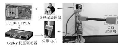
在给出仿真和实验结果之前, 首先简要介绍一下本文的实验平台.如图 4所示, 本文的单关节SEA机器人由机械主体、实时控制系统以及驱动装置三部分组成.在机械主体与驱动装置部分, 机器人可沿电机旋转轴进行平面旋转运动, 驱动源选用Maxon直流伺服电机驱动(减速比N = 1:100), 伺服电机端配有相对码盘(4 000 PPR), 负载端安装有绝对码盘(4 096 PPR), 弹性组件串联于电机和负载之间.对于实时控制部分, 采用运行在Linux-Xenomai实时操作环境下的PC104作为主控制器, 控制周期设定为1 ms.除此之外, 利用FPGA实现了CAN、SSI等总线接口来实现电机端码盘和负载端码盘信号的采集, 将信号处理后传送至PC104, 同时PC104将控制量通过FPGA下发至驱动器, 控制电机完成相应的指令.
3.2 数值仿真验证(Simulation verification)
首先利用仿真来测试本文控制器的控制性能.在仿真实验中, 通过动态调节负载端的参数和受力情况, 模拟了以下三种交互场景.具体而言, 第一组仿真实验为碰撞, 初始时负载端处于自由运动状态, 之后让负载端突然停止; 第二组仿真实验为释放, 初始时刻令负载端保持静止, 之后突然释放负载端让其进入自由运动状态; 第三组仿真为零阻抗控制, 在负载端加入周期的干扰力矩, 并且负载端的动力学参数呈现周期性的连续变化.这三组仿真实验模拟了人-机交互过程中常见的三种情形, 能够很好地验证出控制器面向交互应用的性能.为了体现本文方法的优势, 在此与文献[26-27]中所提的级联PID控制方法进行比较(级联PID控制方法被广泛用于SEA的力矩控制中[10-13, 26-27], 因此在此用作比较).经过调节, 本文设计的控制器相关参数如表 2所示, 级联PID控制器力矩环控制参数调节为$k_{op} = 10$, $k_{oi} = 3$, $k_{od} = 0.5$, 速度环控制参数为$k_{ip} = 3$, $k_{ii} = 1$, $k_{id} = 0$.
表 2 本文控制器的控制参数Table 2 The parameters of the proposed controllerParameter Value l1, l2 10, 50 Γ1, Γ2, Γ3 20, 20, 10 λ 15 k, k1 20, 5 ρ 5 ε 1 仿真实验1.碰撞
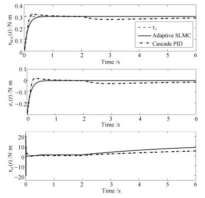
该情形具体描述为, 初始时刻负载端处于自由运动状态, 之后突然发生"碰撞", 负载端运动停止.该仿真的具体过程为, 期望力矩始终保持为$\tau_d=0.3$ N$\cdot$m, 初始时刻负载端的动力学参数设置为
${J_L} = 1{\rm{kg}} \cdot {{\rm{m}}^2},{C_L} = 0.05{\dot \theta _L}{\rm{N}} \cdot {\rm{m}}$
在$t=2$ s时突然将负载端的动力学参数改变为
${J_L} = 500{\rm{kg}} \cdot {{\rm{m}}^2},{C_L} = 10000{\dot \theta _L}{\rm{N}} \cdot {\rm{m}}$
仿真结果如图 5所示.通过图 5中的仿真结果可以看出, 本文控制方法在暂态响应和鲁棒性两方面具有明显的优势, 当"碰撞"发生后, 能够更有效地做出响应, 使SEA维持输出期望力矩.
仿真实验2.释放
该情形具体描述为, 初始时刻负载端处于静止状态, 之后负载端突然进入自由运动状态.该仿真实验的具体过程为, 期望力矩始终保持为$\tau_d=0.3$ N$\cdot$m, 初始时刻负载端的动力学参数设置为
$J_L=500$ kg$\cdot {\rm m}^2$, $C_L$=10 000 $\dot \theta_L$ N$\cdot$m
在$t $= 2 s时突然将负载端的动力学参数改变为
$J_L=1$ kg$\cdot {\rm m}^2$, $C_L$ = 0.05 $\dot \theta_L$ N$\cdot$m
仿真结果如图 6所示.从仿真结果可以看出, 初始阶段负载端处于静止状态, 两种控制方法都能够保证SEA输出力矩达到期望值, 本文方法收敛速度更快, 且无超调量, 具有更好的暂态响应性能.随着仿真中负载参数的突然改变, 负载开始进入加速运动阶段, 本文方法基本不受该变化带来的影响, 而级联PID方法无法在短时间内使输出力矩恢复到期望值, 体现了本文方法拥有更强的鲁棒性, 对交互场景拥有更强的适应能力.
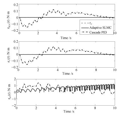
仿真实验3.零阻抗控制
零阻抗控制经常被应用在人-机交互场合, 机器人系统保持零力矩输出以提高"透明度".该仿真实验的具体过程为, 期望力矩为$\tau_d=0$ N$\cdot$m, 负载端加入扰动信号(见式(30)), 且负载端的动力学参数随着负载运动呈现周期性变化, 以此来模拟人-机交互.仿真结果如图 7所示.根据仿真结果可以看出, 相比级联PID控制方法, 本文的控制方法使SEA输出力矩维持在更小的范围内, 能够更好地应对这种交互场景.
${\tau _L} = \left\{ {\begin{array}{*{20}{l}} {\sin (4\pi t),}&{若t \le 2{\rm{s}}}\\ {1 + \sin (8\pi t),}&{若2{\rm{s}} < t \le 6{\rm{s}}}\\ { - 1 + \sin (12\pi t),}&{若6{\rm{s}} < t \le 10{\rm{s}}} \end{array}} \right.$
(30) 3.3 实验验证(Experimental verification)
为进一步验证本文方法的有效性, 本节在如图 6所示的自主搭建的SEA实验平台上进行了实验验证.与仿真相对应, 分别在碰撞、释放和零阻抗控制的交互情景下进行了实验.为了体现本文方法的优越性, 使用级联PID控制方法和级联PID加前馈补偿的控制方法(Feedforward (FF) + PID)作对比.其中本文设计的控制器与级联PID控制器与仿真实验保持一致, 级联PID加前馈补偿控制器设计为: $\tau_M(t)=f(x_1(t))+c_{M0}x_2(t)+\text{PID}(\text{PID}(e_1(t))-x_2(t))$.其中, $c_{M0}$为电机标称阻尼系数, 经过辨识[42]设定为$c_{M0}=0.75$ N$\cdot$ms/rad, 该控制器的外环控制参数调节为$k_{op} = 5$, $k_{oi} = 1.5$, $k_{od} = 0.1$, 内环控制参数为$k_{ip} = 2$, $k_{ii} = 1$, $k_{id} = 0$.值得指出的是, 在实验中力矩值及力矩误差值均是通过式(1)~(4) 计算而得的.接下来, 通过具体的3组实验加以说明.
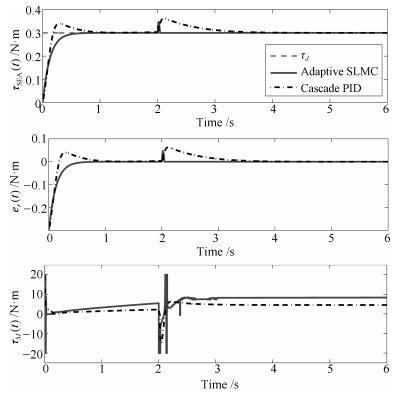
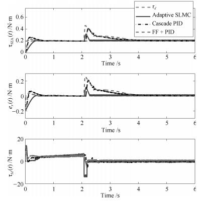
实验1.碰撞
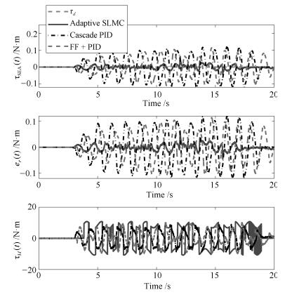
第一组实验的实验结果如图 8所示, 对实验结果进行分析, 相比于级联PID控制方法和前馈结合级联PID的控制方法, 本文方法能使SEA输出力矩更快速地达到期望值, 且在碰撞发生后能够更快地恢复到期望值, 体现了本文方法在暂态响应和鲁棒性两方面的优势.需要指出的是, 在对比实验中, 两次碰撞发生的时刻并不完全相同, 因为在实际实验中很难保证严格的时间同步.
实验2.释放
第二组实验的实验结果如图 9所示, 实验结果表明, 初始时刻, 三种控制方法都能够使SEA的输出力矩收敛至期望值, 但本文方法能够更快地达到期望值且无超调.当负载端被释放后, 本文的方法能够很好地适应这种变化, SEA输出力矩基本没有受到影响.而级联PID控制器和结合前馈补偿的级联PID控制器的性能明显下降, SEA输出力矩无法快速地恢复到期望值.实验结果体现出了本文的控制方法具有更好的鲁棒性, 能够更好地适应交互场景中负载端动力学模型发生变化的情况.同第一组实验一样, 两次释放的时刻也存在着一些偏差.
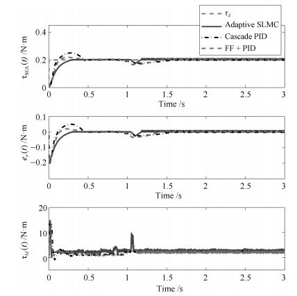
实验3.零阻抗控制
实验3的实验结果如图 10所示, 可以看出, 在本文控制算法的作用下, SEA输出力矩能够保持在很小的范围内, 而在级联PID控制器和结合前馈补偿的级联PID控制器控制下, SEA的力矩输出相对较大, 充分表明了本文控制方法更好的鲁棒性和低阻抗特性.
通过实验结果可以看出, 在无交互的情况下, 本文设计的控制器和结合前馈补偿的级联PID控制器相比级联PID控制器都具有更快的收敛速度, 但本文方法无超调, 体现了更优的暂态响应性能; 在交互过程中, 由于本文的控制方法中加入了运动观测器的观测结果作为前馈项, 能够有效地应对交互过程中负载端发生的变化, 因此能够取得更好的控制效果且有着更优越的鲁棒性能.值得一提的是, 通过对图 5~7和图 8~10进行对比可以发现, 实验结果与仿真结果之间存在着一定的差异, 尤其是控制输入有着明显的不同, 这主要是因为在仿真中未考虑摩擦力的影响, 且实验平台中往往存在着一些建模中未考虑到的动力学因素.
4. 结论
为实现SEA的力矩控制, 本文基于SEA的动力学模型设计了运动观测器和自适应滑模控制器, 并引入了辅助的抗饱和系统来补偿系统饱和限制.与现有的SEA力/力矩控制方法相比, 本文控制方法适用于非线性SEA, 更加通用; 控制器能够很好地应对负载端的变化, 更加适用于交互系统.文中对控制器的性能进行了严格的理论分析, 并通过仿真和实验验证了所提方法的有效性.目前, 实验室正在搭建多关节SEA平台, 在接下来的工作中, 将对多关节SEA的控制问题进行进一步研究.
-
图 3 单关节SEA交互机器人示意图
Fig. 3 Schematic representation of the single SEA interaction robot system
表 1 SEA机械参数
Table 1 The mechanical parameters of the SEA
Parameter Value Ks 13 600 N/m c 0.018 m R 0.020 m r 0.005 m  下载: 导出CSV
表 2 本文控制器的控制参数
Table 2 The parameters of the proposed controller
Parameter Value l1, l2 10, 50 Γ1, Γ2, Γ3 20, 20, 10 λ 15 k, k1 20, 5 ρ 5 ε 1
下载: 导出CSV
-
[1] Pratt G A, Williamson M M. Series elastic actuators. In:Proceedings of the 1995 IEEE/RSJ International Conference on Intelligent Robots and Systems. Pittsburgh, PA, USA:IEEE, 1995. 399-406 [2] 谭民, 王硕.机器人技术研究进展.自动化学报, 2013, 39(7):963-972 http://www.aas.net.cn/CN/abstract/abstract18124.shtmlTan Min, Wang Shuo. Research progress on robotics. Acta Automatica Sinica, 2013, 39(7):963-972 http://www.aas.net.cn/CN/abstract/abstract18124.shtml [3] Vallery H, Veneman J, van Asseldonk E, Ekkelenkamp R, Buss M, van Der Kooij H. Compliant actuation of rehabilitation robots. IEEE Robotics & Automation Magazine, 2008, 15(3):60-69 http://ieeexplore.ieee.org/document/4624584/ [4] Sulzer J S, Roiz R A, Peshkin M A, Patton J L. A highly backdrivable, lightweight knee actuator for investigating gait in stroke. IEEE Transactions on Robotics, 2009, 25(3):539-548 doi: 10.1109/TRO.2009.2019788 [5] 胡进, 侯增广, 陈翼雄, 张峰, 王卫群.下肢康复机器人及其交互控制方法.自动化学报, 2014, 40(11):2377-2390 http://www.aas.net.cn/CN/abstract/abstract18514.shtmlHu Jin, Hou Zeng-Guang, Chen Yi-Xiong, Zhang Feng, Wang Wei-Qun. Lower limb rehabilitation robots and interactive control methods. Acta Automatica Sinica, 2014, 40(11):2377-2390 http://www.aas.net.cn/CN/abstract/abstract18514.shtml [6] Pratt G A, Willisson P, Bolton C, Hofman A. Late motor processing in low-impedance robots:impedance control of series-elastic actuators. In:Proceedings of the 2004 American Control Conference. Boston, MA, USA:IEEE, 2004. 3245-3251 [7] Wyeth G. Demonstrating the safety and performance of a velocity sourced series elastic actuator. In:Proceedings of the 2008 IEEE International Conference on Robotics and Automation. Pasadena, CA, USA:IEEE, 2008. 3642-3647 [8] Vallery H, Ekkelenkamp R, Van Der Kooij H, Buss M. Passive and accurate torque control of series elastic actuators. In:Proceedings of the 2007 IEEE/RSJ International Conference on Intelligent Robots and Systems. San Diego, CA, USA:IEEE, 2007. 3534-3538 [9] Tagliamonte N L, Accoto D. Passivity constraints for the impedance control of series elastic actuators. Proceedings of the Institution of Mechanical Engineers, Part I:Journal of Systems and Control Engineering, 2014, 228(3):138-153 doi: 10.1177/0959651813511615 [10] Oblak J, Matjačić Z. On stability and passivity of haptic devices characterized by a series elastic actuation and considerable end-point mass. In:Proceedings of the 2011 IEEE International Conference on Rehabilitation Robotics. Zurich, Switzerland:IEEE, 2011. 1-5 [11] dos Santos W M, Siqueira A A G. Impedance control of a rotary series elastic actuator for knee rehabilitation. In:Preprints of the 19th World Congress, The International Federation of Automatic Control. Cape Town, South Africa:IFAC, 2014. 4801-4806 [12] Tagliamonte N L, Accoto D, Guglielmelli E. Rendering viscoelasticity with series elastic actuators using cascade control. In:Proceedings of the 2014 IEEE International Conference on Robotics and Automation. Hong Kong, China:IEEE, 2014. 2424-2429 [13] dos Santos W. M, Caurin G. A. P, Siqueira A. A. G, Design and control of an active knee orthosis driven by a rotary series elastic actuator, Control Engineering Practice, 2017, 58(1):307-318 http://www.sciencedirect.com/science/article/pii/S0967066115300198 [14] Kong K, Bae J, Tomizuka M. Control of rotary series elastic actuator for ideal force-mode actuation in human-robot interaction applications. IEEE/ASME Transactions on Mechatronics, 2009, 14(1):105-118 doi: 10.1109/TMECH.2008.2004561 [15] Kong K, Bae J, Tomizuka M. A compact rotary series elastic actuator for human assistive systems. IEEE/ASME Transactions on Mechatronics, 2012, 17(2):288-297 doi: 10.1109/TMECH.2010.2100046 [16] Calanca A, Fiorini P. Human-adaptive control of series elastic actuators. Robotica, 2014, 32(8):1301-1316 doi: 10.1017/S0263574714001519 [17] Calanca A, Capisani L, Fiorini P. Robust force control of series elastic actuators. Actuators, 2014, 3(3):182-204 doi: 10.3390/act3030182 [18] Yoo S, Chung W K. SEA force/torque servo control with model-based robust motion control and link-side motion feedback. In:Proceedings of the 2015 IEEE International Conference on Robotics and Automation. Seattle, WA, USA:IEEE, 2015. 1042-1048 [19] Misgeld B J E, Pomprapa A, Leonhardt S. Robust control of compliant actuators using positive real H2-controller synthesis. In:Proceedings of the 2014 American Control Conference. Portland, OR, USA:IEEE, 2014. 5477-5483 [20] 朱秋国, 熊蓉, 吕铖杰, 毛翊超.新型串联弹性驱动器设计与速度控制.电机与控制学报, 2015, 19(6):83-88 http://www.cnki.com.cn/Article/CJFDTOTAL-DJKZ201506014.htmZhu Qiu-Guo, Xiong Rong, Lv Cheng-Jie, Mao Yi-Chao. Novel series elastic actuator design and velocity control. Electric Machines and Control, 2015, 19(6):83-88 http://www.cnki.com.cn/Article/CJFDTOTAL-DJKZ201506014.htm [21] Ames A D, Holley J. Quadratic program based nonlinear embedded control of series elastic actuators. In:Proceedings of the 53rd IEEE Conference on Decision and Control. Los Angeles, CA, USA:IEEE, 2014. 6291-6298 [22] Powell M J, Ames A D. Hierarchical control of series elastic actuators through control Lyapunov functions. In:Proceedings of the 53rd IEEE Conference on Decision and Control. Los Angeles, CA, USA:IEEE, 2014. 2986-2992 [23] Wolf S, Hirzinger G. A new variable stiffness design:matching requirements of the next robot generation. In:Proceedings of the 2008 IEEE International Conference on Robotics and Automation. Pasadena, CA, USA:IEEE, 2008. 1741-1746 [24] Jafari A, Tsagarakis N G, Caldwell D G. A novel intrinsically energy efficient actuator with adjustable stiffness (AwAS). IEEE/ASME Transactions on Mechatronics, 2013, 18(1):355-365 doi: 10.1109/TMECH.2011.2177098 [25] Furnémont R, Mathijssen G, van der Hoeven T, Brackx B, Lefeber D, Vanderborght B. Torsion MACCEPA:A novel compact compliant actuator designed around the drive axis. In:Proceedings of the 2015 IEEE International Conference on Robotics and Automation. Seattle, WA, USA:IEEE, 2015. 232-237 [26] Laffranchi M, Chen L S, Kashiri N, Lee J, Tsagarakis N G, Caldwell D G. Development and control of a series elastic actuator equipped with a semi active friction damper for human friendly robots. Robotics and Autonomous Systems, 2014, 62(12):1827-1836 doi: 10.1016/j.robot.2014.06.007 [27] Austin J, Schepelmann A, Geyer H. Control and evaluation of series elastic actuators with nonlinear rubber springs. In:Proceedings of the 2015 IEEE/RSJ International Conference on Intelligent Robots and Systems. Hamburg, Germany:IEEE, 2015. 6563-6568 [28] Palli G, Melchiorri C. On the control of redundant robots with variable stiffness actuation. In:Proceedings of the 2012 IEEE/RSJ International Conference on Intelligent Robots and Systems. Algarve, Portugal:IEEE, 2012. 5077-5082 [29] Yu H Y, Huang S, Chen G, Pan Y P, Guo Z. Human-robot interaction control of rehabilitation robots with series elastic actuators. IEEE Transactions on Robotics, 2015, 31(5):1089-1100 doi: 10.1109/TRO.2015.2457314 [30] Garabini M, Passaglia A, Belo F, Salaris P, Bicchi A. Optimality principles in stiffness control:the VSA kick. In:Proceedings of the 2012 IEEE International Conference on Robotics and Automation. Saint Paul, MN, USA:IEEE, 2012. 3341-3346 [31] Braun D, Howard M, Vijayakumar S. Optimal variable stiffness control:formulation and application to explosive movement tasks. Autonomous Robots, 2012, 33(3):237-253 doi: 10.1007/s10514-012-9302-3 [32] Lee J, Laffranchi M, Kashiri N, Tsagarakis N G, Caldwell D G. Model-free force tracking control of piezoelectric actuators:application to variable damping actuator. In:Proceedings of the 2014 IEEE International Conference on Robotics and Automation. Hong Kong, China:IEEE, 2014. 2283-2289 [33] Lee J, Jin M, Tsagarakis N G, Caldwell D G. Terminal sliding-mode based force tracking control of piezoelectric actuators for variable physical damping system. In:Proceedings of the 2014 IEEE/RSJ International Conference on Intelligent Robots and Systems. Chicago, IL, USA:IEEE, 2014. 2407-2413 [34] Wang M, Sun L, Yin W, Dong S, Liu J T. A novel sliding mode control for series elastic actuator torque tracking with an extended disturbance observer. In:Proceedings of the 2015 IEEE International Conference on Robotics and Biomimetics. Zhuhai, China:IEEE, 2015. 2407-2412 [35] Dong S, Zhou L, Wang M, Sun L. Variable stiffness estimation of a series elastic actuator. In:Proceedings of the 2016 Chinese Control Conference. Chengdu, China:IEEE, 2016. 2114-2119 [36] 于哲, 王璐, 苏剑波.基于干扰观测器的不确定线性多变量系统控制.自动化学报, 2014, 40(11):2643-2649 http://www.aas.net.cn/CN/abstract/abstract18542.shtmlYu Zhe, Wang Lu, Su Jian-Bo. Disturbance observer based control for linear multi-variable systems with uncertainties. Acta Automatica Sinica, 2014, 40(11):2643-2649 http://www.aas.net.cn/CN/abstract/abstract18542.shtml [37] Chen W H. Disturbance observer based control for nonlinear systems. IEEE/ASME Transactions on Mechatronics, 2004, 9(4):706-710 doi: 10.1109/TMECH.2004.839034 [38] Li S H, Yang J, Chen W H, Chen X S. Disturbance Observer-Based Control:Methods and Applications. Boca Raton, FL:CRC Press, 2014. [39] 陈晓平, 和卫星, 傅海军.线性系统理论.北京:机械工业出版社, 2011.Chen Xiao-Ping, He Wei-Xing, Fu Hai-Jun. Linear Systems Theory. Beijing:China Machine Press, 2011. [40] 张扬名, 闫鹏.线性电机伺服系统的自适应鲁棒控制.控制理论与应用, 2015, 32(3):287-294 http://www.cnki.com.cn/Article/CJFDTOTAL-KZLY201503002.htmZhang Yang-Ming, Yan Peng. Adaptive robust control for linear motor servo systems. Control Theory & Applications, 2015, 32(3):287-294 http://www.cnki.com.cn/Article/CJFDTOTAL-KZLY201503002.htm [41] Chen M, Ge S S, Ren B B. Adaptive tracking control of uncertain MIMO nonlinear systems with input constraints. Automatica, 2011, 47(3):452-465 doi: 10.1016/j.automatica.2011.01.025 [42] Bae J, Kong K, Tomizuka M. Gait phase-based smoothed sliding mode control for a rotary series elastic actuator installed on the knee joint. In:Proceedings of the 2010 American Control Conference. Baltimore, MD, USA:IEEE, 2010. 6030-6035 -

 下载:
下载:
计量
- 文章访问数: 2015
- HTML全文浏览量: 231
- PDF下载量: 904
- 被引次数: 0
