

-
摘要: 3D打印技术是一种新兴的增材制造技术,许多人认为是一项将要改变世界的“破坏性”技术,并声称该技术将引发新一轮工业革命.本文根据3D打印技术涉及的不同核心成型技术、材料和设备体积等,介绍了3D打印技术的不同分类,综述了主流3D打印过程控制技术,指出了3D打印技术的控制系统存在的问题并提出了产业化进程中的建议和意见.Abstract: 3D printing is a new add manufacturing technology, and many people think it is a "destructive" technology that will change the world, claim it will trigger a new round of industrial revolution. According to 3D printing technology involved in different core forming technologies, materials and equipment volumes, this paper introduces the different classifications of 3D printing technology, overviews the mainstream 3D printing technology control system, discusses the problems existing in the control system of 3D printing, and provides suggestions and advices for the process of industrialization.
-
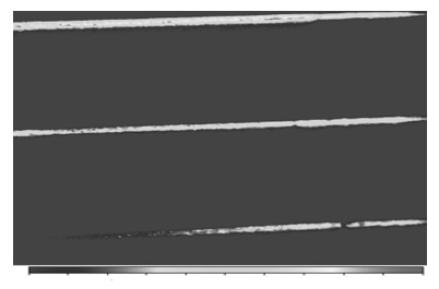
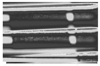
图 14 NIR图像在预热阶段中温区间
Fig. 14 Medium temperature range of NIR images at pre-heating phases
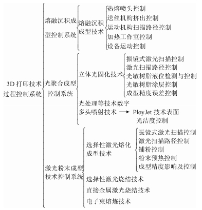
表 1 3D打印技术的分类
Table 1 The classification of 3D printing technology
成型方式(材料) 成型方式名称 3D打印成型技术 熔挤压(热塑性塑料) 熔融沉积成型技术 FDM熔融沉积成型技术 层压(纸、金属膜、塑料薄膜) 分层直接成型技术 LOM分层实体制造技术 粉末粘接(石膏、陶瓷粉末) 粉末粘接成型技术 3DP三维打印粘接成型技术 光聚合(液态光敏树脂) 光聚合成型技术 SLA立体光固化技术,DLP数字光处理技术PloyJet多头喷射技术 粉末烧结/熔融(金属、合金、热塑性、陶瓷等粉末) 激光粉末成型技术 SLS选择性激光烧结技术,DMLS直接金属激光烧结技术SLM选择性激光熔化成型技术,EBM电子束熔炼技术  下载: 导出CSV
表 2 参数V, N, ΔP1和喷嘴孔直径d0稳定喷射关系
Table 2 The stable jetting relations of the parameters V, N, ΔP1 and diameter d0 of the nozzle orifice
实例 流速V (mm/s) 功率N (kW) 压力ΔP1 (mbar) 直径知d0 (mm) 1 30 2.13 170 217 2 34 2.13 180 225 3 28 2.07 180 194 4 28 2.07 190 193 5 32 1.99 300 181 6 26 1.96 320 169 7 26 1.96 360 149 8 30 1.96 290 178
下载: 导出CSV
表 3 已存在的混合路径算法和所提出算法的路径比较
Table 3 Comparison of the proposed method with the existing hybrid method
下载: 导出CSV
表 4 振镜校正实验数据
Table 4 Vibrating mirror calibration experiment data
试验次数 1 2 3 4 5 6 7 第一次X 149.8 0 149.7 149.8 0 149.6 150.3 第一次Y 149.7 150 149.8 0 0 0 150.2 第二次X 150 0 150.2 150.1 0 150.2 149.7 第二次Y 150.2 149.9 150.1 0 0 0 149.8
下载: 导出CSV
-
[1] Butter M, Leis M, Sandtke M, McLean M, Lincoln J, Wilson A. The leverage effect of photonics technologies on the European economy:the European perspective[Online], available:http://www.ec.europa.eu/digital-single-market/news/leverage-effect-photonics-technologies-european-economy-european-perspective, December 29, 2015 [2] Armstrong R, Gregory A. Layers of complexity. The Medical Journal of Australia, 2012, 197(6):311-257 doi: 10.5694/mja12.c0917 [3] 任宇.中国与主要发达国家智能制造的比较研究.工业经济论坛, 2015, (2):68-76 http://www.cnki.com.cn/Article/CJFDTOTAL-IDER201502008.htmRen Yu. A comparative study of intelligent manufacturing between China and the main developed countries. Industrial Economy Review, 2015, (2):68-76 http://www.cnki.com.cn/Article/CJFDTOTAL-IDER201502008.htm [4] Skubic R L, Comb J W, Grudem J K, Swanson W J, Batchelder J S, Brose SM. Viscosity Pump for Extrusion-based Deposition Systems, U.S. Patent 7891964, February 2011 [5] Crump S S. Apparatus and Method for Creating Three-dimensional Objects, U.S. Patent 5121329, June 1992 [6] Valkenaers H, Vogeler F, Ferraris E, Voet A, Kruth J P. A novel approach to additive manufacturing:screw extrusion 3D-printing. In:Proceedings of the 10th International Conference on Multi-Material Micro Manufacture. San Sebastián, Spain:Research Publishing, 2013. 235-238 [7] Batchelder J S, Swanson W J, Johnson K C. Additive Manufacturing Process with Dynamic Heat Flow Control, U.S. Patent 20150097307, April 2013 [8] de Castro Silveira Z, de Freitas M S, Inforçatti Neto P, Noritomi P Y, da Silva J V L. Design development and functional validation of an interchangeable head based on mini screw extrusion applied in an experimental desktop 3-D printer. International Journal of Rapid Manufacturing, 2014, 4(1):49-65 doi: 10.1504/IJRAPIDM.2014.062037 [9] 彭勇刚, 韦巍.基于多段温度控制的熔丝沉积成型3D打印喷头及温控方法, CN Patent 103240883A, 2013年8月Peng Yong-Gang, Wei Wei. Based on Temperature Control of Fuse Deposit Forming 3d Print Heads and the Temperature Control Method, CN Patent 103240883A, August 2013 [10] Astrum K J, Hagglund T. Automatic Tuning of PID Controllers. Washington:Instrumentation Systems, and Automation Society, 1988. 75-85 http://cn.bing.com/academic/profile?id=646286238&encoded=0&v=paper_preview&mkt=zh-cn [11] 莫红, 王飞跃, 赵亮.一一映射下区间二型模糊集合的语言动力学轨迹.模式识别与人工智能, 2010, 23(2):144-147 http://www.cnki.com.cn/Article/CJFDTOTAL-MSSB201002002.htmMo Hong, Wang Fei-Yue, Zhao Liang. LDS trajectories under one-to-one mappings in interval type-2 fuzzy sets. Pattern Recognition and Artificial Intelligence, 2010, 23(2):144-147 http://www.cnki.com.cn/Article/CJFDTOTAL-MSSB201002002.htm [12] 王柏通. 3D打印喷头的温度分析及控制策略研究[硕士学位论文], 湖南师范大学, 中国, 2014 http://cdmd.cnki.com.cn/article/cdmd-10542-1015515272.htmWang Bo-Tong. A Temperature Analysis & Control Strategy on 3D Printing Nozzle[Master dissertation], Hunan Normal University, China, 2014 http://cdmd.cnki.com.cn/article/cdmd-10542-1015515272.htm [13] Vega E J, Cabezas M G, Mu noz-Sánchez B N, Montanero J M, Ga nán-Calvo A M. A novel technique to produce metallic microdrops for additive manufacturing. The International Journal of Advanced Manufacturing Technology, 2014, 70(5-8):1395-1402 doi: 10.1007/s00170-013-5357-3 [14] Swanson W J, Popa M A, Turley P W, Priedeman W R, Hopkins P E Jr, Brose S, Kimm D I, Pollard D L, Hahn A M. Filament Cassette and Loading System, U.S. Patent 6776602, August 2004 [15] Labossiere J E, Eshelman M E. Rapid Prototyping System with Controlled Material Feedstock, U.S. Patent 7384255, June 2008 [16] 闫东升, 曹志清, 孔改荣. FDM工艺送丝驱动机构的摩擦驱动力分析.北京化工大学学报, 2003, 30(3):71-73 http://d.wanfangdata.com.cn/Periodical/bjhgdxxb200303018Yan Dong-Sheng, Cao Zhi-Qing, Kong Gai-Rong. Analysis of the driving force by friction in a driving structure of FDM. Journal of Beijing University of Chemical Technology, 2003, 30(3):71-73 http://d.wanfangdata.com.cn/Periodical/bjhgdxxb200303018 [17] 汪甜田. FDM送丝机构的研究与设计[硕士学位论文], 华中科技大学, 中国, 2007 http://cdmd.cnki.com.cn/article/cdmd-10487-2009037631.htmWang Tian-Tian. The Research & Design on the Feeder in FDM[Master dissertation], Huazhong University of Science & Technology, China, 2007 http://cdmd.cnki.com.cn/article/cdmd-10487-2009037631.htm [18] Ding D H, Pan Z X, Cuiuri D, Li H J. Wire-feed additive manufacturing of metal components:technologies, developments and future interests. The International Journal of Advanced Manufacturing Technology, 2015, 81(1):465-481 http://cn.bing.com/academic/profile?id=1675559242&encoded=0&v=paper_preview&mkt=zh-cn [19] Li Y F, Lau C C. Development of fuzzy algorithms for servo systems. IEEE Control Systems Magazine, 1989, 9(3):65-72 doi: 10.1109/37.24814 [20] Lin F J, Chiu S L. Adaptive fuzzy sliding-mode control for PM synchronous servo motor drives. IEE Proceedings——Control Theory and Applications, 1998, 145(1):63-72 doi: 10.1049/ip-cta:19981683 [21] Wai R J. Adaptive sliding-mode control for induction servomotor drive. IEE Proceedings——Electric Power Applications, 2000, 147(6):553-562 doi: 10.1049/ip-epa:20000628 [22] Lu X S, Lee Y, Yang S F, Hao Y, Evans J R G, Parini C G. Fine lattice structures fabricated by extrusion freeforming:process variables. Journal of Materials Processing Technology, 2009, 209(10):4654-4661 doi: 10.1016/j.jmatprotec.2008.11.039 [23] Sunil V B, Pande S S. Automatic recognition of features from freeform surface CAD models. Computer-Aided Design, 2008, 40(4):502-517 doi: 10.1016/j.cad.2008.01.006 [24] Onuh S O, Hon K K B. Application of the Taguchi method and new hatch styles for quality improvement in stereolithography. Proceedings of the Institution of Mechanical Engineers, Part B:Journal of Engineering Manufacture, 1998, 212(6):461-472 doi: 10.1243/0954405981515761 [25] Jin Y A, He Y, Xue G H, Fu J Z. A parallel-based path generation method for fused deposition modeling. The International Journal of Advanced Manufacturing Technology, 2015, 77(5-8):927-937 doi: 10.1007/s00170-014-6530-z [26] Wasser T, Jayal A D, Pistor C. Implementation and evaluation of novel buildstyles in fused deposition modeling (FDM). Strain, 1999, 5(6):425-430 [27] Kim D S. Polygon offsetting using a Voronoi diagram and two stacks. Computer-Aided Design, 1998, 30(14):1069-1076 doi: 10.1016/S0010-4485(98)00063-3 [28] Bertoldi M, Yardimci M A, Pistor C M, Gücceri S I. Domain decomposition and space filling curves in toolpath planning and generation. In:Proceedings of the Solid Freeform Fabrication Symposium. Texas, USA:Texas Academic Press, 1998. 267-274 [29] Shi Y, Zhang W, Cheng Y, Huang S. Compound scan mode developed from subarea and contour scan mode for selective laser sintering. International Journal of Machine Tools and Manufacture, 2007, 47(6):873-883 doi: 10.1016/j.ijmachtools.2006.08.013 [30] Yang Y, Fuh J Y H, Loh H T. An efficient scanning pattern for layered manufacturing processes. In:Proceedings of the 2001 IEEE International Conference on Robotics and Automation. Seoul, South Korea:IEEE, 2001. 1340-1345 [31] Ding D H, Pan Z X, Cuiuri D, Li H J. A tool-path generation strategy for wire and arc additive manufacturing. The International Journal of Advanced Manufacturing Technology, 2014, 73(1-4):173-183 doi: 10.1007/s00170-014-5808-5 [32] Batchelder J S, Crump S S. Method for Rapid Prototyping of Solid Models, U.S. Patent 5866058, February 1999 [33] Swanson W J, Turley P W, Leavitt P J, Karwoski P J, Labossiere J E, Skubic R L. High Temperature Modeling Apparatus, U.S. Patent 6722872, April 2004 [34] Costa S, Duarte F, Covas J A. Using MATLAB to Compute Heat Transfer in Free Form Extrusion. Croatia:INTECH Open Access Publisher, 2011. 82-93 http://cn.bing.com/academic/profile?id=2096277459&encoded=0&v=paper_preview&mkt=zh-cn [35] Ji L B, Zhou T R. Finite element simulation of temperature field in fused deposition modeling. Advanced Materials Research, 2010, 97-101:2585-2588 doi: 10.4028/www.scientific.net/AMR.97-101 [36] Zhang Y, Chou Y K. Three-dimensional finite element analysis simulations of the fused deposition modelling process. Proceedings of the Institution of Mechanical Engineers, Part B:Journal of Engineering Manufacture, 2006, 220(10):1663-1671 doi: 10.1243/09544054JEM572 [37] Skubic R L, Comb J W. Adjustable Platform Assembly for Digital Manufacturing System, U.S. Patent 8153183, April 2012 [38] Cavill B R, Schulz R A. Print Head Motor Control System with Automatic Drive Parameter Calculations, U.S. Patent 4775945, October 1988 [39] Hercog D, Curkovič M, Jezernik K. DSP based rapid control prototyping systems for engineering education and research. In:Proceedings of Computer Aided Control System Design, 2006 IEEE International Conference on Control Applications. Munich, Germany:IEEE, 2006. 2292-2297 [40] Ricci F, Le-Huy H. An FPGA-based rapid prototyping platform for variable-speed drives. In:Proceedings of the 28th Annual Conference on the Industrial Electronics Society. Sevilla, Spain:IEEE, 2002. 1156-1161 [41] 魏大忠, 徐健, 吴任东, 张人佶.基于McT运动控制器的快速成型机数控系统研究.组合机床与自动化加工技术, 2003, (4):35-37 http://www.cnki.com.cn/Article/CJFDTOTAL-ZJYC200308011.htmWei Da-Zhong, Xu Jian, Wu Ren-Dong, Zhang Ren-Ji. Based on the fast molding machine CNC system of McT motion controller. Modular Machine Tool & Automatic Manufacturing Technique, 2003, (4):35-37 http://www.cnki.com.cn/Article/CJFDTOTAL-ZJYC200308011.htm [42] Swartz J, Barkan E, Harrison S A. Portable Laser Scanning System and Scanning Methods, U.S. Patent 4387297, January 1983 [43] Roorda A, Romero-Borja F, Donnelly W J III, Queener H, Hebert T J, Campbell M C W. Adaptive optics scanning laser ophthalmoscopy. Optics Express, 2002, 10(9):405-412 doi: 10.1364/OE.10.000405 [44] 杨志卿, 吴登喜, 郑永超.二维光学扫描中扫描角度非线性研究.激光技术, 2004, 3(28):263-265 http://www.cnki.com.cn/Article/CJFDTOTAL-JGJS200403011.htmYang Zhi-Qing, Wu Deng-Xi, Zheng Yong-Chao. Study of angular non-linearity in 2-D optical scanning. Laser Technology, 2004, 3(28):263-265 http://www.cnki.com.cn/Article/CJFDTOTAL-JGJS200403011.htm [45] Stafne M A, Mitchell L D, West R L. Positional calibration of galvanometric scanners used in laser Doppler vibrometers. Measurement, 2000, 28(1):47-59 doi: 10.1016/S0263-2241(00)00006-3 [46] Xie J, Huang S H, Duan Z C. Positional correction algorithm of a laser galvanometric scanning system used in rapid prototyping manufacturing. The International Journal of Advanced Manufacturing Technology, 2005, 26(11-12):1348-1352 doi: 10.1007/s00170-004-2200-x [47] Ehrmann J S. Optics for vector scanning. In:Proceedings of the the SPIE, Beam deflection and scanning technologies. Boston, American:SPIE, 1991. 245-256 [48] 文世峰.选择性激光烧结快速成形中振镜扫描与控制系统的研究[博士学位论文], 华中科技大学, 中国, 2010 http://cdmd.cnki.com.cn/article/cdmd-10487-2010184436.htmWen Shi-Feng. Study of Galvanometric Scan and Control System in Selective Laser Sintering[Ph.D. dissertation], Huazhong University of Science & Technology, China, 2010 http://cdmd.cnki.com.cn/article/cdmd-10487-2010184436.htm [49] Jablonowski D P, Raamot J. Beam deflection at high accuracy and precision. In:Proceedings of SPIE 0084, Laser Scanning Components and Techniques:Design Considerations. San Diego:SPIE, 1977. 69-77 [50] 李广亚, 王玉增, 韩婧茹, 刘双源.机械零件RP中振镜系统校正的几何算法.机床与液压, 2014, 42(19):28-30 http://www.cnki.com.cn/Article/CJFDTOTAL-JCYY201419008.htmLi Guang-Ya, Wang Yu-Zeng, Han Jing-Ru, Liu Shuang-Yuan. Geometry algorithm of galvanometer system correction for rapid prototyping of machine parts. Machine Tool & Hydraulics, 2014, 42(19):28-30 http://www.cnki.com.cn/Article/CJFDTOTAL-JCYY201419008.htm [51] Ngoi B K A, Venkatakrishnan K, Tan B, Noël N, Shen Z W, Chin C S. Two-axis-scanning laser Doppler vibrometer for microstructure. Optics Communications, 2000, 182(1-3):175-185 doi: 10.1016/S0030-4018(00)00762-8 [52] Spence S T, Tarnoff H L. Apparatus and Method for Correcting for Drift in Production of Objects by Stereolithography, U.S. Patent 5059021, October 1991 [53] Spence S T. Apparatus and Method for Profiling a Beam, U.S. Patent 5267013, November 1993 [54] Spence S T, Almquist T A, Tarnoff H L, Juran W. Apparatus and Method for Calibrating and Normalizing a Stereolithographic Apparatus, U.S. Patent 5495328, February 1996 [55] 莫健华, 冯昕, 潘翔.光固化成形系统激光光斑位置漂移校正研究.激光杂志, 2007, 28(4):77-78 http://www.cnki.com.cn/Article/CJFDTOTAL-JGZZ200704041.htmMo Jian-Hua, Feng Xin, Pan Xiang. A research into drift correction of laser spot position in SLA. Laser Journal, 2007, 28(4):77-78 http://www.cnki.com.cn/Article/CJFDTOTAL-JGZZ200704041.htm [56] 祝萍.光固化成形系统光斑检测与坐标漂移校正研究[硕士学位论文], 华中科技大学, 中国, 2006 http://cdmd.cnki.com.cn/article/cdmd-10487-2008022376.htmZhu Ping. A Research into the Measurement of Laser Beam Parameters and Correction of Scanning System Drift in Stereolithography Apparatus[Master dissertation], Huazhong University of Science & Technology, China, 2006 http://cdmd.cnki.com.cn/article/cdmd-10487-2008022376.htm [57] Berumen S, Bechmann F, Lindner S, Kruth J P, Craeghs T. Quality control of laser-and powder bed-based additive manufacturing (AM) technologies. Physics Procedia, 2010, 5(8):617-622 http://cn.bing.com/academic/profile?id=1963661623&encoded=0&v=paper_preview&mkt=zh-cn [58] 王青岗, 颜永年.光固化向量扫描过程中的能量控制.清华大学学报(自然科学版), 2006, 45(11):1456-1459 http://www.cnki.com.cn/Article/CJFDTOTAL-QHXB200511004.htmWang Qing-Gang, Yan Yong-Nian. Energy control in vector scanning of stereolithography. Journal of Tsinghua University (Science and Technology), 2006, 45(11):1456-1459 http://www.cnki.com.cn/Article/CJFDTOTAL-QHXB200511004.htm [59] Abderyim P, Osama H, Tadahiro F, Norishige C. Accurate and efficient drawing method for laser projection. The Journal of the Society for Art and Science, 2008, 7(4):155-169 doi: 10.3756/artsci.7.155 [60] Jacobs P F. Stereolithography and other RP & M Technologies:from Rapid Prototyping to Rapid Tooling. Michigan:American Society of Mechanical Engineers, 1995. 35-42 http://cn.bing.com/academic/profile?id=1494804381&encoded=0&v=paper_preview&mkt=zh-cn [61] Kawasaki A, Goto M, Yashiro H, Ozaki H. An array-type PSD (position-sensitive detector) for light pattern measurement. Sensors and Actuators A:Physical, 1990, 22(1-3):529-533 doi: 10.1016/0924-4247(89)80030-5 [62] Farnworth W M. Layer Thickness Control for Stereolithography Utilizing Variable Liquid Elevation and Laser Focal Length, U.S. Patent 6955783, October 2005 [63] Almquist T A, Modrek B, Jacobs P F, Lewis C W, Lewis M A, Liran A, Cohen A L, Smalley D R. Method of and Apparatus for Measuring and Controlling Fluid Level in Stereolithography, U.S. Patent 5258146, November 1993 [64] Yamamoto M, Itoh K. Three-dimensional Structure Forming Apparatus Provided with a Liquid-level Control System for a Main Resin Tank, U.S. Patent 5248249, September 1993 [65] Stonesmith M, Hunter D, Wahlstrom B, Stout L, Reynolds G. Rapid Prototyping and Manufacturing System and Method, U.S. Patent 658105527 B2, September 2005 [66] Renap K, Kruth J P. Recoating issues in stereolithography. Rapid Prototyping Journal, 1995, 1(3):4-16 doi: 10.1108/13552549510094223 [67] Almquist T A, Hull C W, Modrek B, Jacobs P F, Lewis C W, Cohen A L. Recoating of Stereolithographic Layers, U.S. Patent 5651934, July 1997 [68] Almquist T A, Hull C W, Modrek B, Jacobs P F, Lewis C W, Cohen A L. Recoating of Stereolithographic Layers, U.S. Patent 6048487, April 2000 [69] 范准峰.光固化快速成形涂层技术研究[硕士学位论文], 华中科技大学, 中国, 2006 http://cdmd.cnki.com.cn/article/cdmd-10487-2008022236.htmFan Zhun-Feng. Research on Recoating Technology of Stereolithography Rapid Prototyping[Master dissertation], Huazhong University of Science & Technology, China, 2006 http://cdmd.cnki.com.cn/article/cdmd-10487-2008022236.htm [70] Ang B Y, Chua C K, Du Z H. Study of trapped material in rapid prototyping parts. The International Journal of Advanced Manufacturing Technology, 2000, 16(2):120-130 doi: 10.1007/s001700050017 [71] Almquist T A, Hull C W, Thayer J S, Leyden R N, Jacobs P F, Smalley D R. Rapid Recoating of Three-dimensional Objects Formed on a Cross-sectional Basis, U.S. Patent 5902537, May 1999 [72] Zhou C, Chen Y, Yang Z G, Khoshnevis B. Digital material fabrication using mask-image-projection-based stereolithography. Rapid Prototyping Journal, 2013, 19(3):153-165 doi: 10.1108/13552541311312148 [73] 赵万华, 李涤尘, 柯映林.光固化快速成形中树脂涂层技术研究.中国机械工程, 1999, 10(12):1333-1345 http://www.cnki.com.cn/Article/CJFDTOTAL-ZGJX199912004.htmZhao Wan-Hua, Li Di-Chen, Ke Ying-Lin. Research on resin recoating technology of stereolithography rapid prototyping. China Mechanical Engineering, 1999, 10(12):1333-1345 http://www.cnki.com.cn/Article/CJFDTOTAL-ZGJX199912004.htm [74] Gilio M, Kruth J P, Vanherck P. High-speed curtain recoating for stereolithography. In:Proceedings of the 12th Annual Solid Freeform Fabrication Symposium. Texas, USA:Texas Academic Press, 2001. 46-54 [75] Yan Y N, Li S J, Zhang R J, Lin F, Wu R D, Lu Q D, Lu Q P, Xiong Z, Wang X H. Rapid prototyping and manufacturing technology:principle, representative technics, applications, and development trends. Tsinghua Science & Technology, 2009, 14(1):1-12 http://cn.bing.com/academic/profile?id=2161302514&encoded=0&v=paper_preview&mkt=zh-cn [76] Onuh S O, Hon K K B. Optimising build parameters for improved surface finish in stereolithography. International Journal of Machine Tools and Manufacture, 1998, 38(4):329-342 doi: 10.1016/S0890-6955(97)00068-0 [77] 习俊通, 周满元, 严隽琪.基于STEP的非均匀自适应分层方法.计算机集成制造系统报, 2004, 10(2):235-239 http://www.cnki.com.cn/Article/CJFDTOTAL-JSJJ200402022.htmXi Jun-Tong, Zhou Man-Yuan, Yan Jun-Qi. STEP-based approach of adaptive slicing with non-uniform cusp heights for rapid prototyping. Computer Integrated Manufacturing Systems, 2004, 10(2):235-239 http://www.cnki.com.cn/Article/CJFDTOTAL-JSJJ200402022.htm [78] Horton L, Gargiulo E, Keefe M. An experimental study of the parameters affecting curl in parts created using stereolithography. In:Proceedings of the Solid Freeform Fabrication Symposium. Texas, USA:Texas Academic Press, 1993. 178-185 [79] Corcione C E, Greco A, Maffezzoli A. Photopolymerization kinetics of an epoxy-based resin for stereolithography. Journal of applied polymer science, 2004, 92(6):3484-3491 doi: 10.1002/(ISSN)1097-4628 [80] Jacobs P F. Rapid Prototyping and Manufacturing:Fundamentals of Stereolithography. Dearborn, MI:SME, 1992. 135-141 http://cn.bing.com/academic/profile?id=1523127134&encoded=0&v=paper_preview&mkt=zh-cn [81] 马雷, 李涤尘, 段玉岗, 卢秉恒.基于二次曝光原理的光固化快速成型工艺研究.西安交通大学学报, 2001, 35(1):57-60 http://www.cnki.com.cn/Article/CJFDTOTAL-XAJT200101013.htmMa Lei, Li Di-Chen, Duan Yu-Gang, Lu Bing-Heng. Stereolithography process based on double exposal method. Journal of Xi'an Jiaotong University, 2001, 35(1):57-60 http://www.cnki.com.cn/Article/CJFDTOTAL-XAJT200101013.htm [82] 袁慧羚, 周天瑞.光固化快速成型工艺的精度研究.南方金属, 2009, (2):24-27 http://www.cnki.com.cn/Article/CJFDTOTAL-NFGT200902008.htmYuan Hui-Ling, Zhou Tian-Rui. A study of the fabrication precision of rapid prototyping by stereo lithography. Southern Metals, 2009, (2):24-27 http://www.cnki.com.cn/Article/CJFDTOTAL-NFGT200902008.htm [83] Deckard C R. Method and Apparatus for Producing Parts by Selective Sintering, U.S. Patent 4863538, September 1989 [84] Hagiwara M, Sassa M. Powder Rapid Prototyping Apparatus and Powder Rapid Prototyping Method, U.S. Patent 9061465, June 2015 [85] Nakano S, Shimizu T, Hagiwara M, Sassa M. Rapid Prototyping Model, Powder Rapid Prototyping Apparatus and Powder Rapid Prototyping Method, U.S. Patent 20150050463A1, February 2015 [86] Budding A, Vaneker T H J. New strategies for powder compaction in powder-based rapid prototyping techniques. Procedia CIRP, 2013, 6:527-532 doi: 10.1016/j.procir.2013.03.100 [87] Beaman J J, Deckard C R. Selective Laser Sintering with Assisted Powder Handling, U.S. Patent 4938816, July 1990 [88] Bourell D L, Marcus H L, Barlow J W, Beaman J J, Deckard C R. Multiple Material Systems for Selective Beam Sintering, U.S. Patent 5382308, January 1995 [89] Forderhase P F, Deckard C R, Klein J M. Apparatus and Method for Producing Parts with Multi-directional Powder Delivery, U.S. Patent 252264, October 1993 [90] Cox B D. Laser Sintering Powder Recycle System, U.S. Patent 7887316, March 2005 [91] Cox B D. Selective Laser Sintering Powder Recycle System, U.S. Patent 7887316, February 2011 [92] Cox B D. Pneumatic Powder Transport System, U.S. Patent 7296599, November 2007 [93] 晏耐生, 林峰, 齐海波, 陆伟, 张靖.电子束选区熔化技术中可控振动落粉铺粉系统的研究.中国机械工程, 2010, (19):2379-2382 http://www.cnki.com.cn/Article/CJFDTOTAL-ZGJX201019023.htmYan Nai-Sheng, Lin Feng, Qi Hai-Bo, Lu Wei, Zhang Jing. Study on controllable vibration powder spreading system in electron beam selective melting. China Mechanical Engineering, 2010, (19):2379-2382 http://www.cnki.com.cn/Article/CJFDTOTAL-ZGJX201019023.htm [94] 程军.选择性激光烧结预热温度场的数值模拟及实验研究[硕士学位论文], 华中科技大学, 中国, 2006 http://www.doc88.com/p-3176625698485.htmlCheng Jun. Numerical Simulation and Experimental Study of Temperature Field in the Preheating Process of SLS[Master dissertation], Huazhong University of Science & Technology, China, 2006 http://www.doc88.com/p-3176625698485.html [95] Grube K W, Beaman J J. Radiant Heating Apparatus for Providing Uniform Surface Temperature Useful in Selective Laser Sintering, U.S. Patent 5155321, October 1992 [96] Philippi J. Radiant Heater for Heating the Building Material in a Laser Sintering Device, U.S. Patent 8073315, December 2011 [97] Price S, Cooper K, Chou K. Evaluations of temperature measurements by near-infrared thermography in powder-based electron-beam additive manufacturing. In:Proceedings of the Solid Freeform Fabrication Symposium. Texas, USA:Texas Academic Press, 2012. 761-773 [98] Yang H J, Hwang P J, Lee S H. A study on shrinkage compensation of the SLS process by using the Taguchi method. International Journal of Machine Tools and Manufacture, 2002, 42(11):1203-1212 doi: 10.1016/S0890-6955(02)00070-6 [99] Li X F, Dong J H. Study on curve of Pe-heating temperature control in selective laser sintering. In:Proceedings of the 2009 International Symposium on Web Information Systems and Applications. Nanchang, China, 2009. 156-158 [100] 冯文仙. HRPS-ⅢA选择性激光烧结机预热系统的研究[硕士学位论文], 华中科技大学, 中国, 2003 http://www.docin.com/p-1374316010.htmlFeng Wen-Xian. Study on Preheating System of HRPS-ⅢA Selective Laser Sintering Machine[Master dissertation], Huazhong University of Science & Technology, China, 2003 http://www.docin.com/p-1374316010.html [101] 钟建伟, 史玉升, 蔡道生, 黄树槐.选择性激光烧结预热温度的自适应控制研究.机械科学与技术, 2004, 23(11):1370-1373 http://www.cnki.com.cn/Article/CJFDTOTAL-JXKX200411029.htmZhong Jian-Wei, Shi Yu-Sheng, Cai Dao-Sheng, Huang Shu-Huai. Investigation on the adaptive control preheating in selective laser sintering (SLS). Mechanical Science and Technology, 2004, 23(11):1370-1373 http://www.cnki.com.cn/Article/CJFDTOTAL-JXKX200411029.htm [102] 董星涛, 周子裕, 卢德林, 洪亮亮, 阮耀波. SLS预热温度场温度补偿研究.机电工程, 2010, 27(5):31-34 http://www.cnki.com.cn/Article/CJFDTOTAL-JDGC201005009.htmDong Xing-Tao, Zhou Zi-Yu, Lu De-Lin, Hong Liang-Liang, Ruan Yao-Bo. Study of temperature compensation based on preheating temperature field for SLS. Journal of Mechanical and Electrical Engineering, 2010, 27(5):31-34 http://www.cnki.com.cn/Article/CJFDTOTAL-JDGC201005009.htm [103] Beaman J J, Barlow J W, Bourell D L, Crawford R H, Marcus H L, McAlea K P. Solid Freeform Fabrication:a New Direction in Manufacturing. US:Springer, 1997. 25-49 http://cn.bing.com/academic/profile?id=1546192049&encoded=0&v=paper_preview&mkt=zh-cn [104] Bugeda Miguel Cervera G, Lombera G. Numerical prediction of temperature and density distributions in selective laser sintering processes. Rapid Prototyping Journal, 1999, 5(1):21-26 doi: 10.1108/13552549910251846 [105] Dai K, Shaw L. Distortion minimization of laser-processed components through control of laser scanning patterns. Rapid Prototyping Journal, 2002, 8(5):270-276 doi: 10.1108/13552540210451732 [106] 王文峰.覆膜金属粉末激光烧结成型过程三维温度场数值模拟技术研究[硕士学位论文], 中北大学, 中国, 2008 http://cdmd.cnki.com.cn/article/cdmd-10110-2008142702.htmWang Wen-Feng. Study on Numerical Simulation of 3D Temperature Field During Selective Laser Sintering Polymer-coated Metal Powder[Master dissertation], North University of China, China, 2008 http://cdmd.cnki.com.cn/article/cdmd-10110-2008142702.htm [107] Wang X W. Calibration of shrinkage and beam offset in SLS process. Rapid Prototyping Journal, 1999, 5(3):129-133 doi: 10.1108/13552549910278955 [108] Williams J D, Deckard C R. Advances in modeling the effects of selected parameters on the SLS process. Rapid Prototyping Journal, 1998, 4(2):90-100 doi: 10.1108/13552549810210257 [109] Wang W L, Cheah C M, Fuh J Y H, Lu L. Influence of process parameters on stereolithography part shrinkage. Materials & Design, 1996, 17(4):205-213 http://cn.bing.com/academic/profile?id=2026812759&encoded=0&v=paper_preview&mkt=zh-cn [110] Raghunath N, Pandey P M. Improving accuracy through shrinkage modelling by using Taguchi method in selective laser sintering. International Journal of Machine Tools and Manufacture, 2007, 47(6):985-995 doi: 10.1016/j.ijmachtools.2006.07.001 [111] 魏潇然, 耿国华, 张雨禾.熔丝沉积制造中稳固低耗支撑结构生成.自动化学报, 2016, 42(1):98-106 http://www.aas.net.cn/CN/abstract/abstract18799.shtmlWei Xiao-Ran, Geng Guo-Hua, Zhang Yu-He. Steady and low consuming supporting for fused deposition modeling. Acta Automatica Sinica, 2016, 42(1):98-106 http://www.aas.net.cn/CN/abstract/abstract18799.shtml [112] 王飞跃.从社会计算到社会制造:一场即将来临的产业革命.中国科学院院刊, 2012, 27(6):658-669 http://www.cnki.com.cn/Article/CJFDTOTAL-KYYX201206001.htmWang Fei-Yue. From social computing to social manufacturing:the coming industrial revolution and new frontier in cyber-physical-social space. Bulletin of the Chinese Academy of Sciences, 2012, 27(6):658-669 http://www.cnki.com.cn/Article/CJFDTOTAL-KYYX201206001.htm -


计量
- 文章访问数: 3780
- HTML全文浏览量: 1138
- PDF下载量: 2097
- 被引次数: 0
